

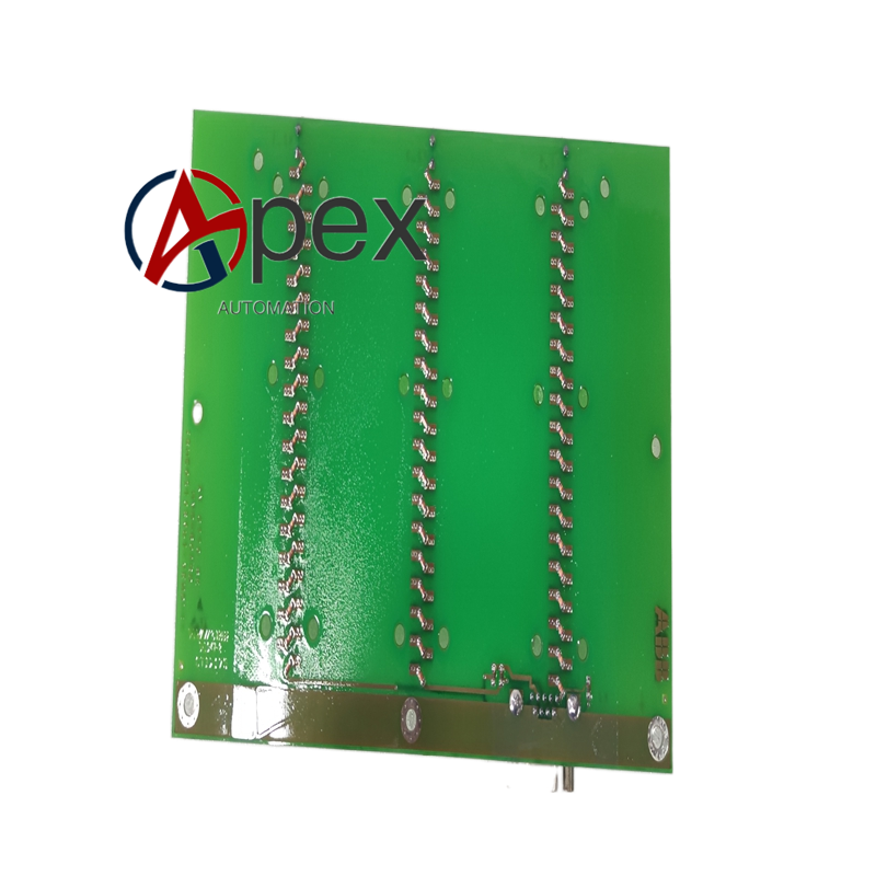

Technical Specifications Multiple communication interface channels. Auxiliary power supplied by excitation rack, typical power consumption 6.6 W. Operating temperature ‑10 ℃ to +55 ℃, storage temperature ‑40 ℃ to +85 ℃, non‑condensing relative humidity 5%‑95%. Conformal coated circuit board.
Functional Features Realizes multi‑protocol data communication for excitation system. Uploads generator operating parameters, alarm information and fault event logs. Receives remote parameter setting and control commands from upper‑level system. On‑board LED indicates communication channel running status. Built‑in hardware self‑diagnosis for communication‑link faults.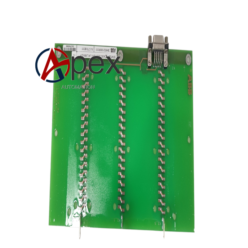
Application Scenarios Spare‑part for UNITROL series generator excitation systems in power plants and industrial power stations. Used for system maintenance and spare‑part replacement.
Performance Parameters Stable long‑term data transmission performance. High‑efficiency data interaction between excitation controller and upper‑level system. Self‑diagnosis accurately captures communication‑link interruption and interface abnormality.
Material Composition Multilayer glass‑fiber epoxy printed circuit board. Communication processing chips, signal isolation assemblies. Conformal protective coating. Back‑plane plug‑in connectors and external communication ports.
Structural Characteristics Plug‑in circuit board matching excitation cabinet rack slot. Board edge equipped with back‑plane bus connector and external communication interface ports. Reserved mechanical fixing holes. Weight approximately 0.63 kilogram.
Working Principle After power‑on, board completes hardware self‑check and communication‑parameter initialization. It exchanges data with excitation main controller via back‑plane bus. Operating data and fault records are packaged and sent to upper‑level monitoring equipment through external communication ports.
Installation Requirements Cut off excitation rack auxiliary power before replacement. Insert XVC770BE101 3BHE021083R0101 into designated slot and tighten fixing screws. Confirm back‑plane connector is fully engaged. Complete external communication cable wiring. Restore power supply and verify communication‑link data interaction.
Usage Notes Take anti‑static protection measures during handling. Avoid damage to conformal coating layer. Prohibit hot‑plug operation under powered condition. Verify communication parameter configuration after board replacement.




There are no reviews yet.