

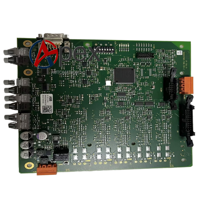
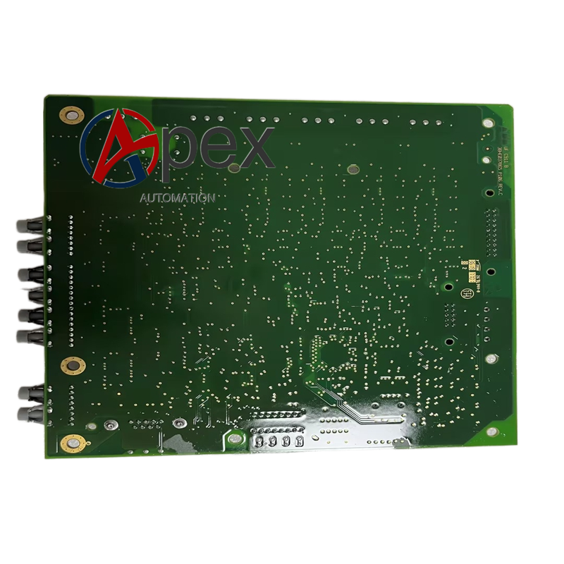

Technical Specifications Multi‑channel AC and DC power sampling input, optimized power conversion circuit. Auxiliary power supplied by excitation rack, typical power consumption 7.5 W. Operating temperature ‑10 ℃ to +60 ℃, storage temperature ‑40 ℃ to +85 ℃, non‑condensing relative humidity 5%‑95%. Conformal coated surface, channel isolation voltage 2000 V AC.
Functional Features High‑precision sampling for excitation power unit voltage and current. Optimized internal power conversion circuit. Output power‑supply abnormal alarm signal. Enhanced hardware self‑diagnosis coverage. Improved EMC anti‑interference capability. On‑board LED reflects power and fault state.
Application Scenarios Used for upgrading replacement and spare‑part maintenance of power plant generator excitation system. Mechanically compatible with corresponding excitation rack hardware.
Performance Parameters Improved sampling accuracy for power‑loop feedback signals. Enhanced anti‑interference performance for strong electromagnetic field site environment. Self‑diagnosis covers more power circuit fault types.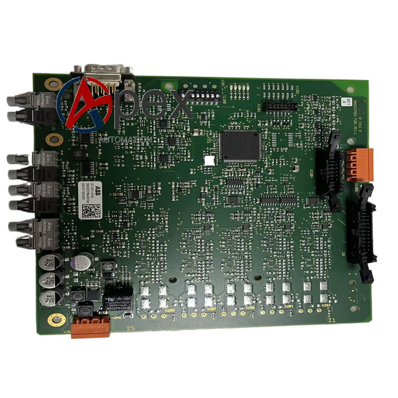
Material Composition Multilayer glass‑fiber epoxy printed circuit board with anti‑interference layout. High‑precision sampling components, power conversion chips, optocoupler isolation assemblies. Conformal protective coating.
Structural Characteristics Plug‑in board with same mechanical dimension as UFC911B101 for interchangeable installation. Board edge equipped with back‑plane connector and signal terminals. Reserved fixing holes. Weight approximately 0.65 kilogram.
Working Principle After power‑on, board completes hardware self‑check. It continuously collects power‑loop voltage and current feedback signals. Signals are conditioned and transmitted to excitation regulator board through back‑plane connector. Internal circuit realizes stable power conversion for on‑board components. Diagnosis circuit monitors power‑loop and hardware status in real‑time.
Installation Requirements Cut off all power sources of excitation cabinet before installation. Insert UFC911B110 into target slot and tighten fixing screws. Confirm connectors are fully engaged. Restore power supply and complete power‑sampling calibration and excitation system function test.
Usage Notes Adopt anti‑static protection during disassembly‑assembly. Do not scratch conformal coating layer. Hot‑plug operation is forbidden. Complete whole‑machine simulation test after installation.




There are no reviews yet.