

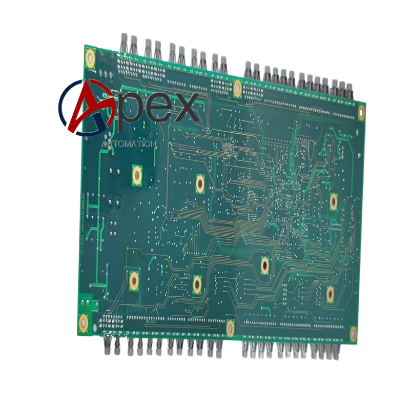

Technical Specifications Multi‑channel isolated digital input and relay drive output channels. Auxiliary power supplied by system rack, typical power consumption 7.2 W. Operating temperature ‑10 ℃ to +55 ℃, storage temperature ‑40 ℃ to +85 ℃, non‑condensing relative humidity 5%‑95%. Conformal coated surface, isolation voltage 2000 V AC between field loop and internal logic circuit.
Functional Features Receives and isolates multi‑path external equipment status signals. Provides multi‑group relay output for field device control. On‑board LED reflects each channel working condition. Built‑in hardware self‑diagnosis function detects board‑level circuit abnormality. Conformal coating improves adaptability to humid and dusty cabinet environment.
Application Scenarios Spare‑part component for generator excitation system and large‑capacity industrial drive equipment. Applied for maintenance and spare‑part replacement of power plant and heavy‑industry automation devices.
Performance Parameters Stable signal transmission of all channels under long‑term operation. Galvanic isolation effectively restrains field‑side electromagnetic interference. Self‑diagnosis function captures hardware fault rapidly.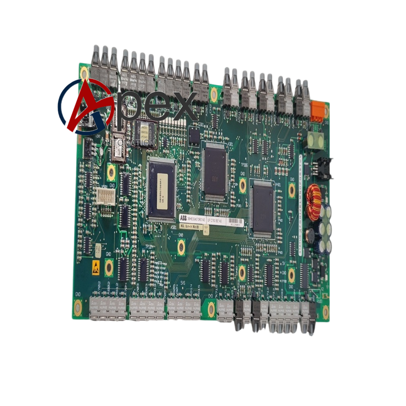
Material Composition Multilayer glass‑fiber epoxy printed circuit board. Signal conditioning chip, optocoupler isolation and multi‑group relay drive assemblies.
Structural Characteristics Plug‑in circuit board structure matching cabinet internal slot. Board edge equipped with back‑plane connector and multi‑channel signal terminals. Mechanical fixing holes for installation.
Working Principle Control commands from main control unit transmit to this board via back‑plane connector. After isolation and drive processing, relay contacts output control signals to external secondary‑loop equipment. External device status signals access terminals, pass conditioning‑isolation circuit and feed back status information to main control unit. Internal diagnosis circuit monitors hardware running state continuously.
Installation Requirements Completely cut off rack auxiliary power before replacement. Make sure connectors are fully inserted and locked. Restore power‑supply, check LED channel status and complete whole‑system function verification test.
Usage Notes Adopt anti‑static wrist strap during disassembly‑assembly. Avoid scratching conformal coating surface. Hot‑plug operation is forbidden.




There are no reviews yet.