

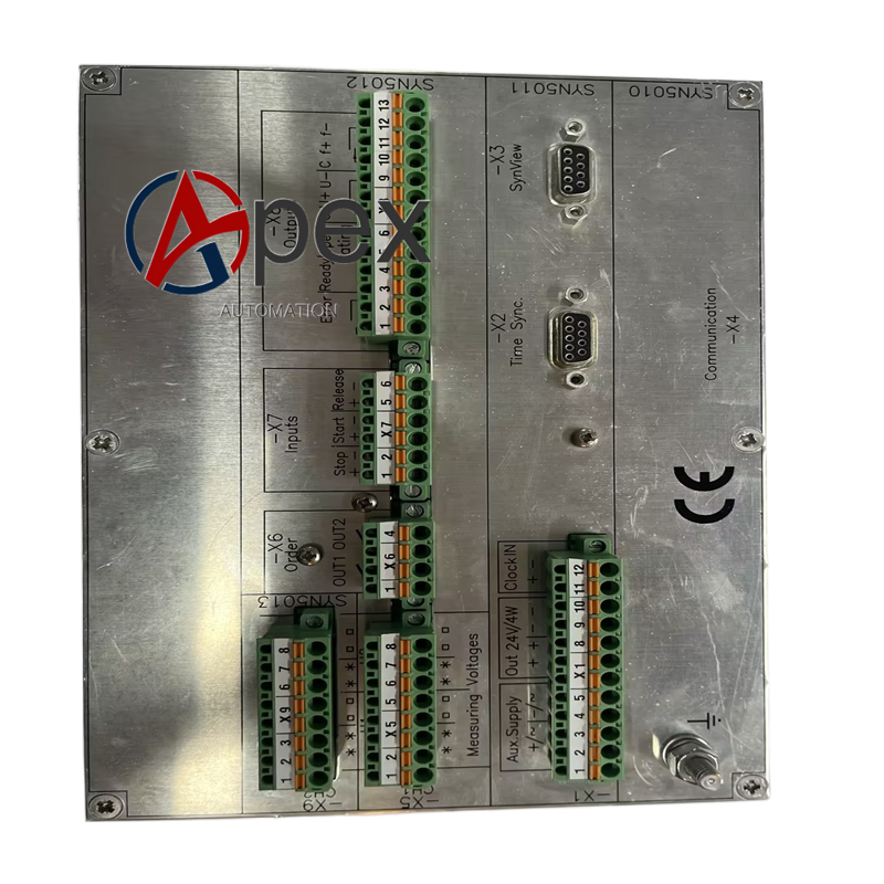

Technical Specifications Rated voltage input 100 V AC. Auxiliary power supply 80‑265 V AC/DC. Typical power consumption 7.8 W. Operating temperature ‑10 ℃ to +60 ℃, storage temperature ‑40 ℃ to +85 ℃, non‑condensing relative humidity 5%‑95%. Module surface IP20. Complies with IEC 60255 power equipment standards.
Functional Features Supports automatic and manual synchronization modes. High‑precision comparison for voltage, frequency and phase difference. Enhanced EMC anti‑interference performance. Outputs dry‑contact closing control signal. Front‑panel multi‑LED indicates synchronization progress and fault alarm. Expanded hardware self‑diagnosis coverage.
Application Scenarios Applied for high‑requirement generator grid‑connection control in thermal power, hydropower and large‑scale industrial power station. Used for upgrading replacement of SYN5202‑0271 and spare‑part maintenance.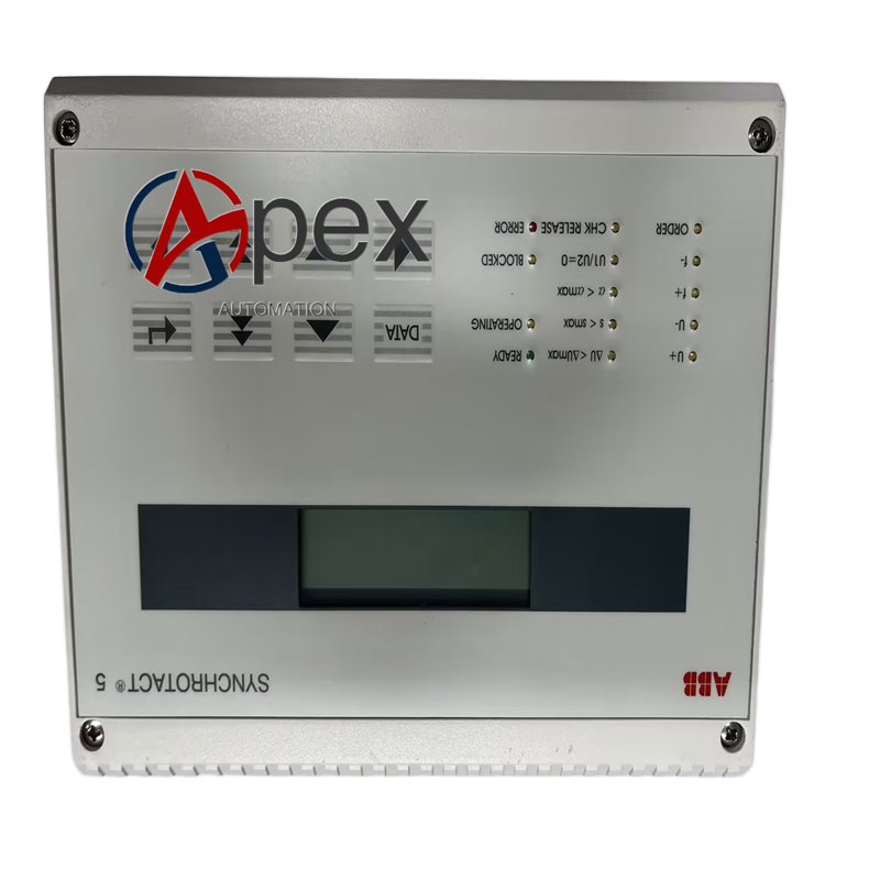
Performance Parameters Higher sampling precision for voltage and phase angle. Synchronization judgment adapts to strong electromagnetic interference site. Contact output keeps stable under long‑term operation. Fault diagnosis covers more internal circuit nodes.
Material Composition Multilayer glass‑fiber epoxy printed circuit board with anti‑interference layout. Synchronization processing chip, high‑precision sampling components. Reinforced plastic housing. Screw‑type secondary‑circuit wiring terminals. Metal rack‑mount fixing support.
Structural Characteristics Standard rack‑mount mechanical dimension, interchangeable with SYN5202‑0271. Front‑panel arranged with LED status indicators. Rear side fitted with signal input, power supply and output terminals.
Working Principle After power‑on, module completes hardware self‑check. It receives PT secondary voltage signal from generator and busbar. Internal high‑precision circuit calculates voltage, frequency and phase difference. When all synchronization threshold conditions are satisfied, module outputs closing dry‑contact signal.
Installation Requirements Install module into standard cabinet rack position and tighten fixing screws. Complete PT voltage input, auxiliary power and closing‑loop wiring strictly according to electrical drawing. Ensure cabinet protective grounding.
Usage Notes Prevent PT secondary short‑circuit during wiring work. Comply with power‑system safety operation rules. Back‑up synchronization configuration parameters. Periodically inspect terminal fastening condition. Complete grid‑connection simulation test after module replacement.




There are no reviews yet.