

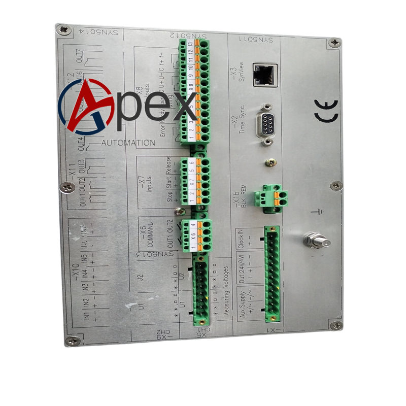
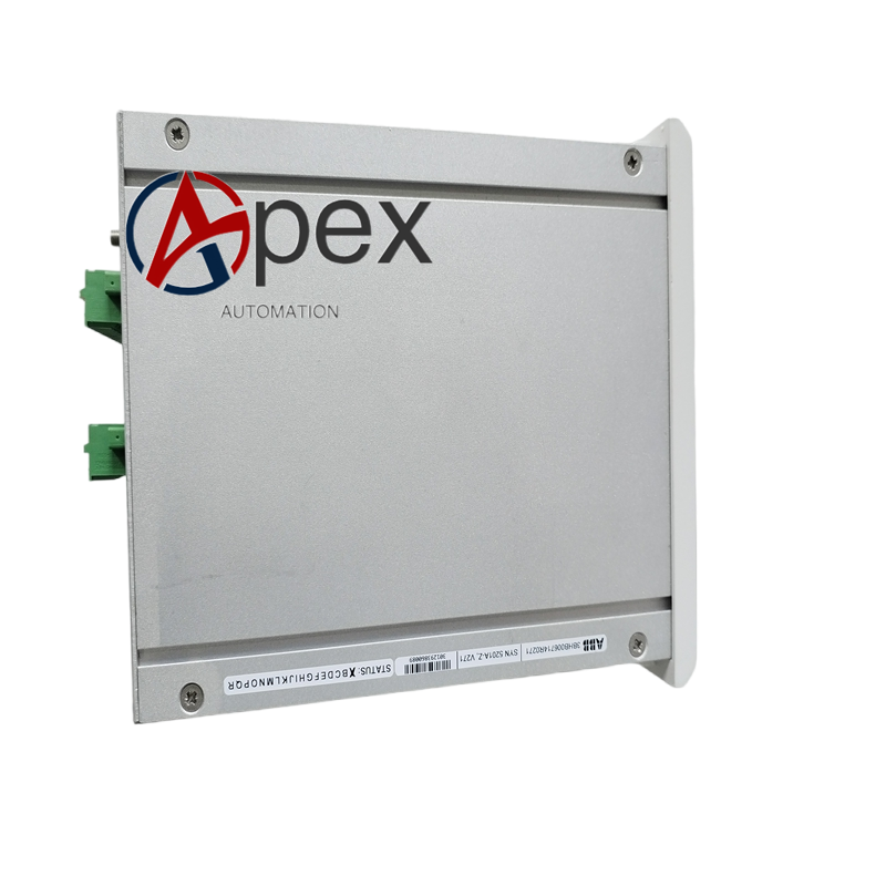

Technical Specifications Voltage sampling input 100 V AC. Auxiliary power supply 24 V DC. Typical power consumption 6.8 W. Operating temperature 0 ℃ to +60 ℃, storage temperature ‑40 ℃ to +85 ℃, non‑condensing relative humidity 5%‑95%. Isolation voltage 1500 V AC for signal channel. Conformal coating treatment. Complies with generator synchronization industry standards.
Functional Features Samples voltage, frequency and phase difference between generator and grid busbar. Executes synchronization logic calculation. Outputs accurate breaker closing trigger pulse. On‑board LED displays working status and fault alarm. Built‑in hardware self‑diagnosis function.
Application Scenarios Applied for generator grid‑connection control in thermal power, hydropower and distributed power station. Used for unit renovation and spare‑part replacement of synchronization cabinet.
Performance Parameters Phase difference and frequency difference calculation maintains high precision. Closing pulse output responds at correct synchronization window. 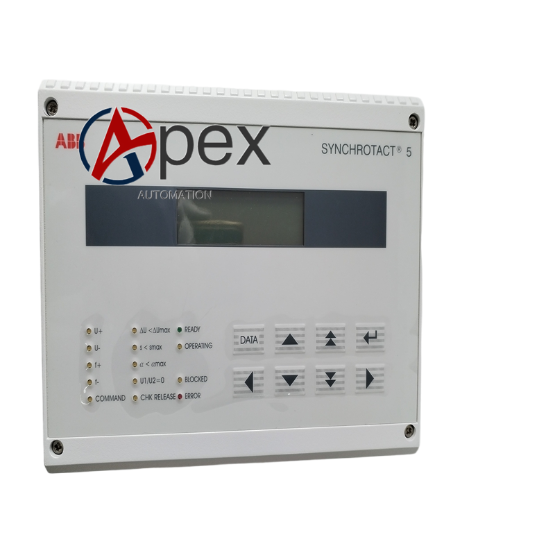
Material Composition Multilayer glass‑fiber epoxy printed circuit board. Voltage sampling chip, synchronization logic processor. Conformal protective coating. Multi‑pin plug‑in connectors.
Structural Characteristics Plug‑in circuit board structure for cabinet internal slot installation. Board edge fitted with back‑plane connector and signal terminals. Reserved mechanical fixing holes. Weight approximately 0.58 kilogram.
Working Principle After power‑on, board completes hardware self‑check. It receives voltage signal from generator PT and grid PT. Internal processor calculates frequency, voltage amplitude and phase difference. When all synchronization conditions are satisfied, it outputs closing pulse signal to generator breaker loop.
Installation Requirements Cut off cabinet power before installation. Insert board into designated slot and fasten fixing screws. Complete PT signal input and pulse output wiring strictly follow generator synchronization schematic drawing.
Usage Notes Adopt anti‑static protection during handling. PT secondary circuit wiring shall comply with power safety rules. Do not plug‑and‑unplug board under powered condition. Periodically inspect terminal tightening condition. Execute simulation synchronization test after board replacement.




There are no reviews yet.