


Technical Specifications Voltage input 100‑125 V AC, current input 1 A / 5 A CT secondary. Auxiliary power supply 80‑265 V AC/DC. Typical power consumption ≤30 W. Transfer action time reaches 30 ms. Operating temperature ‑10 ℃ to +55 ℃, storage temperature ‑40 ℃ to +85 ℃, non‑condensing relative humidity 5%‑95%. Module surface IP20. Complies with IEC 60255 relay protection standards.
Functional Features Samples voltage and current signal from voltage transformer and current transformer. Executes multiple‑mode high‑speed bus transfer logic. Outputs control command for vacuum circuit breaker. Built‑in fault event recording function. Supports local parameter setting and external communication data uploading. Front‑panel display and LED indicate running status and fault information.
Application Scenarios Applied for medium‑voltage power supply system of power plant, large‑scale chemical and metallurgy enterprise. Protects critical motor loads and production process against power‑supply interruption.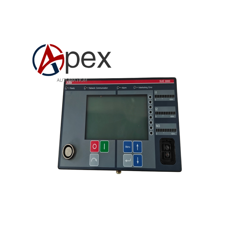
Performance Parameters Fast transfer time minimizes production‑interruption risk. Multiple transfer modes adapt different power‑supply working conditions. Event recording stores multiple groups of fault and transfer records.
Material Composition Metal alloy rack‑mount housing. Industrial‑grade processing chip, voltage and current sampling circuit. Liquid‑crystal display and operation button assembly.
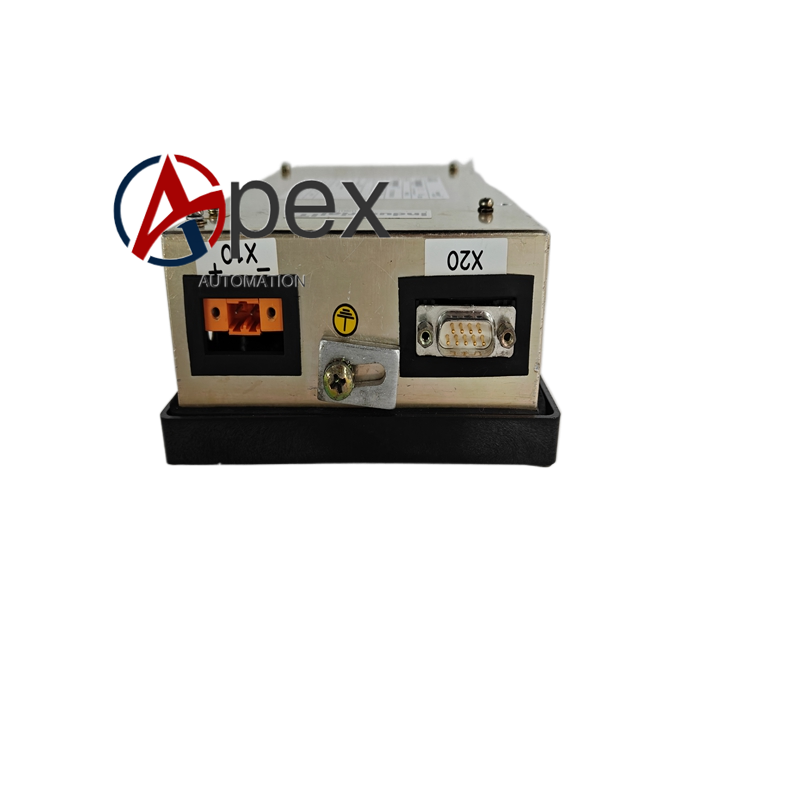
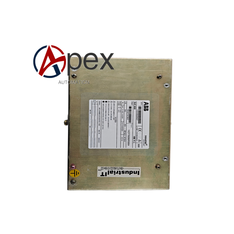
Structural Characteristics Standard rack‑mount housing structure. Front‑panel equipped with display screen and operation buttons. Rear side arranges VT/CT input, auxiliary power, breaker control output and communication terminals. Weight approximately 2.8 kilogram.
Working Principle After power‑on, device completes hardware self‑check. It continuously samples voltage and current signal of working power source and backup power source. Internal logic unit judges power‑supply failure condition according to setting parameters.
Installation Requirements Install device into standard cabinet rack position and fasten fixing screws. Complete VT, CT secondary circuit, auxiliary power supply and breaker control loop wiring strictly follow power‑system engineering drawing.
Usage Notes Secondary current loop must not keep open‑circuit state. Avoid strong electromagnetic interference environment. Back‑up configuration parameters before parameter modification.




There are no reviews yet.