

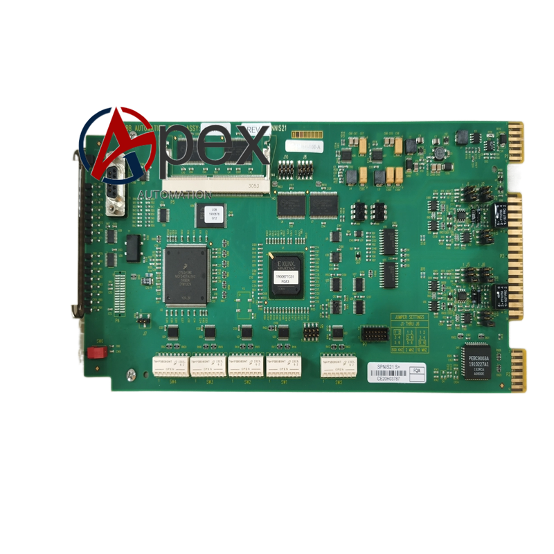
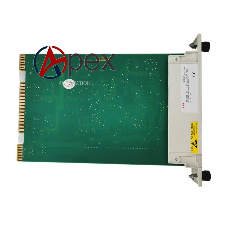

Technical Specifications InfiNet coaxial loop interface and dual 10/100 Mbps Ethernet ports. Auxiliary power supply 24 V DC, typical power consumption 5.0 W. Operating temperature ‑25 ℃ to +65 ℃, storage temperature ‑40 ℃ to +85 ℃, non‑condensing relative humidity 5%‑95%. Channel‑to‑back‑plane isolation voltage 1500 V AC. Module surface IP20. Complies with CE and UL industrial standards.
Functional Features Realizes bidirectional protocol conversion between InfiNet bus and Ethernet. Dual‑Ethernet port supports higher‑grade network redundancy. Optimized hardware fault diagnosis logic. Front‑panel multi‑LED indicators reflect power, running, fault and two‑channel network status. Supports hot‑swap replacement. Supports remote reading of module diagnostic registers via network.
Application Scenarios Applied for high‑reliability DCS control network of thermal power, chemical and metallurgy industries. Used for transformation and upgrading of original SPNIS21 configuration. 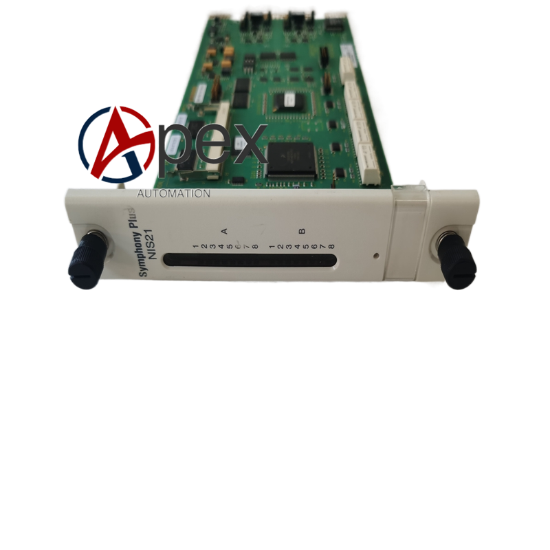
Performance Parameters InfiNet loop communication rate 2 Mbit/s, Ethernet 10/100 Mbit/s auto‑negotiation. Redundancy switching time is less than 10 ms. Enhanced EMC resistance adapts to strong electromagnetic interference site.
Material Composition Multilayer glass‑fiber epoxy printed circuit board with enhanced anti‑interference layout. Network processing chip, isolation and signal drive components. Reinforced plastic module housing. Screw‑type wiring terminals. Copper‑alloy back‑plane plug‑in contact pieces.
Structural Characteristics Rack‑mount plug‑in module structure, mechanical dimension keeps consistent with SPNIS21 for direct replacement. Front panel arranges LED indicators for dual‑network channel. Rear side connects rack back‑plane bus. Weight approximately 0.59 kilogram.
Working Principle After power‑on, module completes hardware self‑check and communication initialization. It processes uplink and downlink data between InfiNet control loop and dual‑Ethernet channels. Internal enhanced diagnosis circuit monitors hardware circuit and communication link status in real‑time. Fault information can be uploaded to upper host system.
Installation Requirements Insert module into designated rack slot and tighten locking screw. Connect 24 V DC auxiliary power supply. Complete InfiNet coaxial cable and dual‑Ethernet wiring according to engineering drawing. Ensure cabinet protective grounding.




There are no reviews yet.