

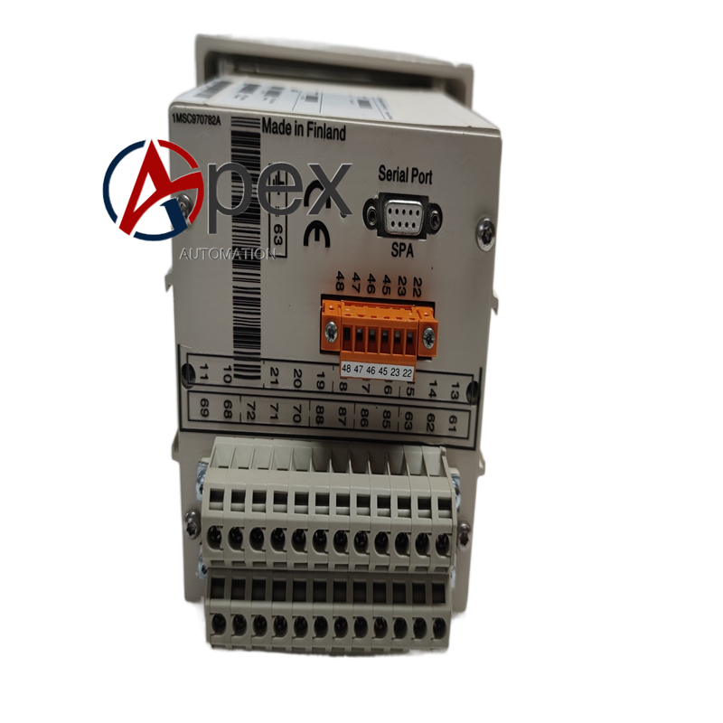

Technical Specifications Over‑voltage, under‑voltage and residual‑voltage protection. Rated voltage input 100 V. Auxiliary power supply 80‑265 V AC/DC. Operating temperature ‑25 ℃ to +70 ℃, storage temperature ‑40 ℃ to +85 ℃, non‑condensing relative humidity 5%‑95%. Front‑panel IP40, rear terminal area IP20. Complies with IEC 60255 relay protection standards.
Functional Features Configurable voltage protection threshold and time‑delay parameters. Completes voltage parameter measurement. Front‑panel display shows measured value, fault record and setting parameters. Relay contact outputs trip and alarm signal. Built‑in fault event recording function.
Application Scenarios Applied for bus‑bar and feeder voltage protection of power plant and distribution substation. Used for power distribution system construction, renovation and spare‑part replacement.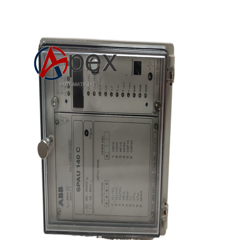
Performance Parameters Protection action time satisfies voltage protection coordination requirement. Measurement accuracy meets site monitoring demand. Local storage supports multiple fault event records. Relay contact has long mechanical service life.
Material Composition Metal alloy housing. Industrial‑grade protection processing chip, voltage sampling circuit. LCD display and operation button assembly. Screw‑type voltage input terminals. Copper‑alloy relay contact components.
Structural Characteristics Standard panel‑mount housing structure. Front‑panel equipped with display screen and operation buttons. Rear side arranges VT input, power supply and output contact terminals. Standard relay panel installation dimension. Weight approximately 1.75 kilogram.
Working Principle After power‑on, relay completes hardware self‑check. It samples voltage signal from voltage transformer. Internal protection unit executes voltage protection algorithm according to setting parameters.
Installation Requirements Install relay on cabinet front panel and fasten mounting accessories. Complete VT input, auxiliary power supply and output loop wiring strictly follow protection schematic drawing. Ensure cabinet protective grounding.
Usage Notes Do not exceed rated voltage input range. Take anti‑interference measure for VT secondary loop. Periodically check terminal tightening condition. Back‑up setting parameters before modification. Follow power safety operation specification during commissioning.




There are no reviews yet.