

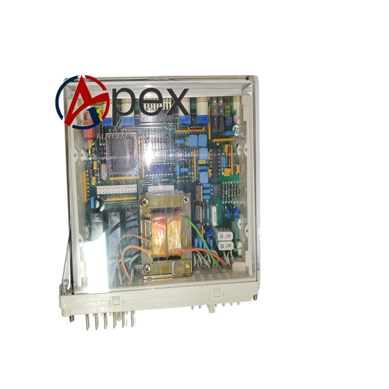

Technical Specifications Multi‑pole test switch structure, short‑circuit self‑locking function for CT loop. Rated working current 5 A, rated voltage 250 V AC/DC. Mechanical operation life reaches 20000 cycles. Operating temperature ‑25 ℃ to +70 ℃, storage temperature ‑40 ℃ to +85 ℃, non‑condensing relative humidity 5%‑95%. Front‑panel IP30, rear connector area IP20. Complies with IEC power secondary test component standards.
Functional Features Realizes safe isolation for CT and VT secondary circuit during protection device commissioning and maintenance. Built‑in CT automatic short‑circuit function prevents current transformer open‑circuit risk. Supports external test instrument access. Front‑panel operation handle realizes switch state switching. Clear mechanical position indication.
Application Scenarios Installed inside substation protection relay rack. Used for protection device commissioning, function test and on‑site maintenance. Widely applied in power plant and substation secondary protection system.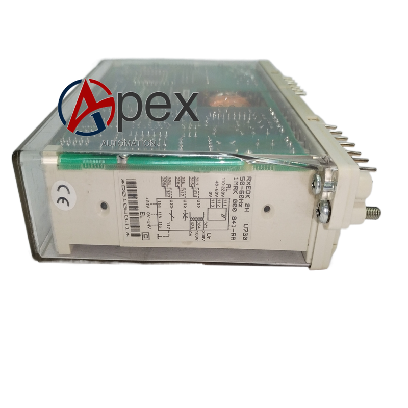
Performance Parameters Switch contact contact resistance keeps low level. CT short‑circuit mechanism acts reliably. Mechanical position indication is accurate. Mechanical service life satisfies on‑site repeated operation requirement.
Working Principle When operating front‑panel handle, internal multi‑pole contact completes loop switching. When module is pulled out or switch is turned to test position, CT loop automatically triggers short‑circuit mechanism to avoid CT open‑circuit hazard. Secondary circuit is isolated from protection device, meanwhile test port is connected for external instrument input.
Installation Requirements Insert module into standard relay rack slot and lock fastening screw. Ensure back‑plane connector contacts are in good condition. Confirm mechanical position indication is correct after installation. Comply with power safety specification during operation. Guarantee rack protective grounding.




There are no reviews yet.