

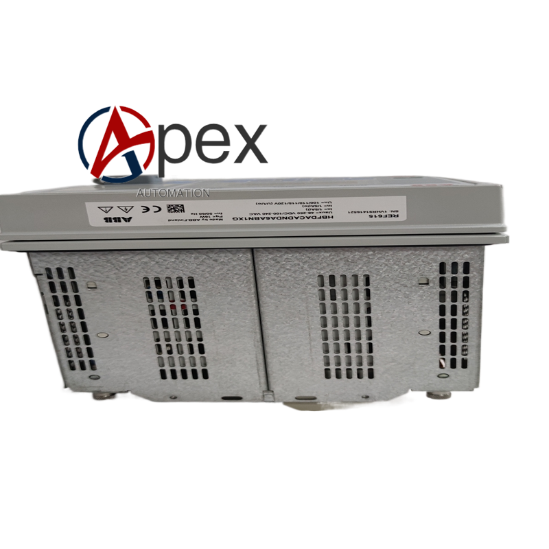
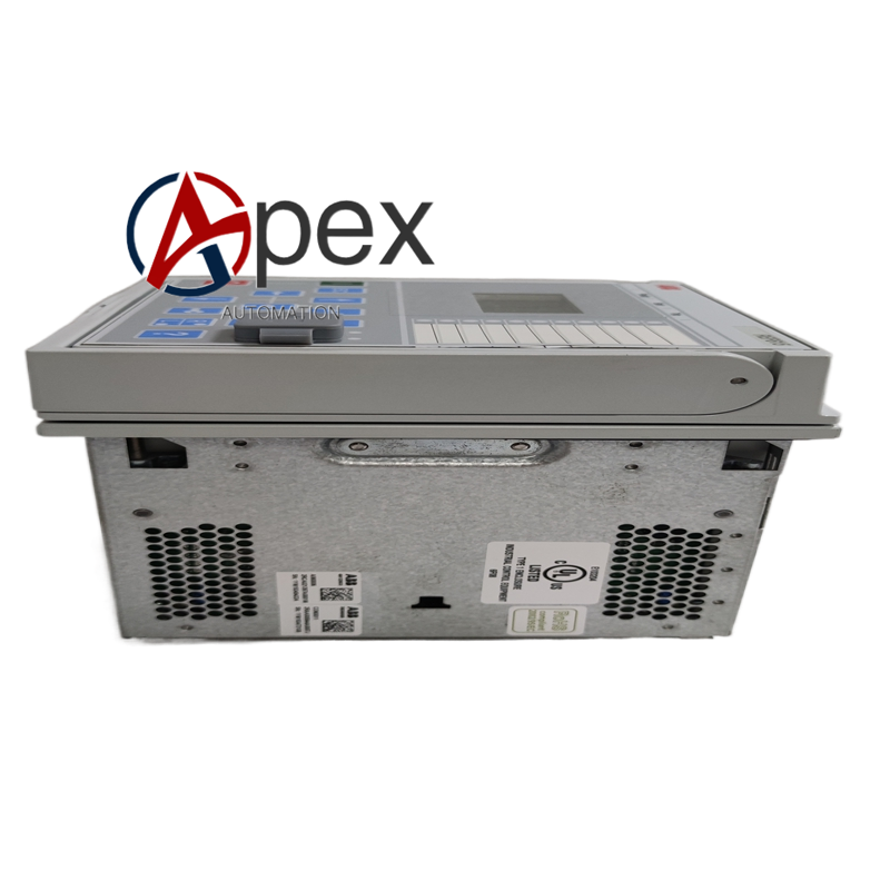

Technical Specifications Complete over‑current, earth‑fault, directional and negative‑sequence protection function library. Custom‑configured analog input, binary input and binary output channels. Supports IEC61850, Modbus TCP, IEC60870‑5‑103 communication protocols. Auxiliary power supply 80‑250 V DC / 85‑265 V AC. Typical power consumption 13.4 W. Operating temperature ‑25 ℃ to +55 ℃, storage temperature ‑40 ℃ to +85 ℃, non‑condensing relative humidity 5%‑95%. Front‑panel IP40, rear terminal‑side IP20. Complies with CE and IEC standards.
Functional Features Implements multi‑function protection for medium‑voltage distribution feeders. Measures multi‑group electrical parameters including current, voltage, power and energy. Collects position signals of circuit‑breakers and disconnectors, supports local and remote switchgear control. Saves fault event records and high‑resolution disturbance waveform data. Front‑panel man‑machine interface realizes local status viewing and parameter modification. LED indicator array displays power, running, trip and alarm information. Built‑in hardware self‑diagnosis detects internal component faults and outputs alarm signals.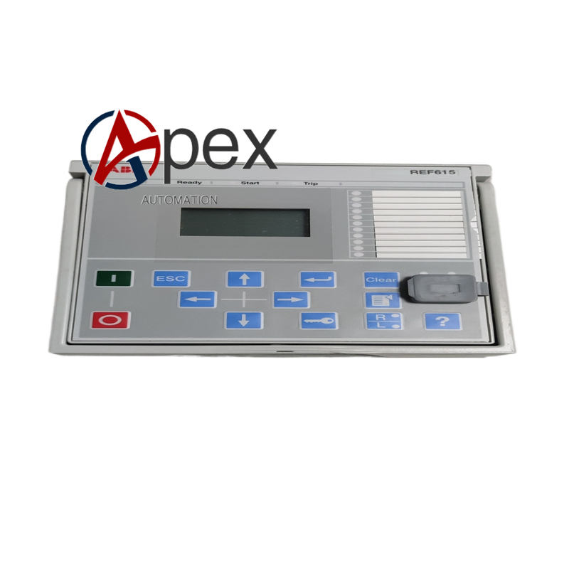
Application Scenarios Mounted inside medium‑voltage switchgear cabinet. Used for feeder protection and control of utility and industrial medium‑voltage power distribution systems. Suitable for distribution automation projects with customized hardware configuration demands.
Performance Parameters Protection response time meets medium‑voltage power grid protection requirements. Disturbance recorder captures fault transient sampling data. Event log supports millisecond‑level time‑stamp recording. Measurement accuracy satisfies industrial distribution monitoring standards. Internal hardware faults generate definite alarm output.
Installation Requirements Fix device firmly inside medium‑voltage switchgear cabinet. Connect auxiliary power supply strictly within rated voltage range. Complete CT, VT and binary‑loop wiring according to engineering schematic drawings. Connect communication cables for remote monitoring function. Download protection settings and project configuration files through supporting engineering software. Implement reliable protective grounding complying with power industry specifications. Verify front‑panel LED working status after power‑on.




There are no reviews yet.