


Technical Specifications Each PM865HI CPU adopts high‑integrity 32‑bit RISC processor with 96 MHz clock frequency. RAM capacity per CPU unit is 32 MB, flash memory is 16 MB for firmware and safety application storage. Rated power supply 24 V DC, acceptable input voltage range 19.2‑30 V DC. Single unit typical power consumption is 15.8 W. Operating temperature 0 ℃‑60 ℃, non‑condensing relative humidity 5%‑95%. Each CPU unit carries dual 10/100 Mbps Ethernet ports, ModuleBus, CEX‑Bus, redundancy control link and dual redundant power input terminals. Each CPU supports maximum twelve CEX‑Bus peripheral modules. Protection class IP20 for cabinet‑mount installation. Every CPU obtains SIL3 functional safety certification complying with IEC61508 standard. Satisfies industrial EMC immunity standard for heavy electromagnetic interference environment.
Functional Features Supports safety‑related and standard IEC61131‑3 programming languages for safety instrumented system. Built‑in 1+1 hot‑standby redundancy, primary‑standby safety‑data synchronization runs continuously, bumpless switch‑over occurs upon primary CPU safety‑related fault. Enhanced high‑integrity self‑diagnosis monitors CPU operation, memory integrity, power supply status and all communication channels for both CPU units, covers safety‑monitoring circuit fault detection. 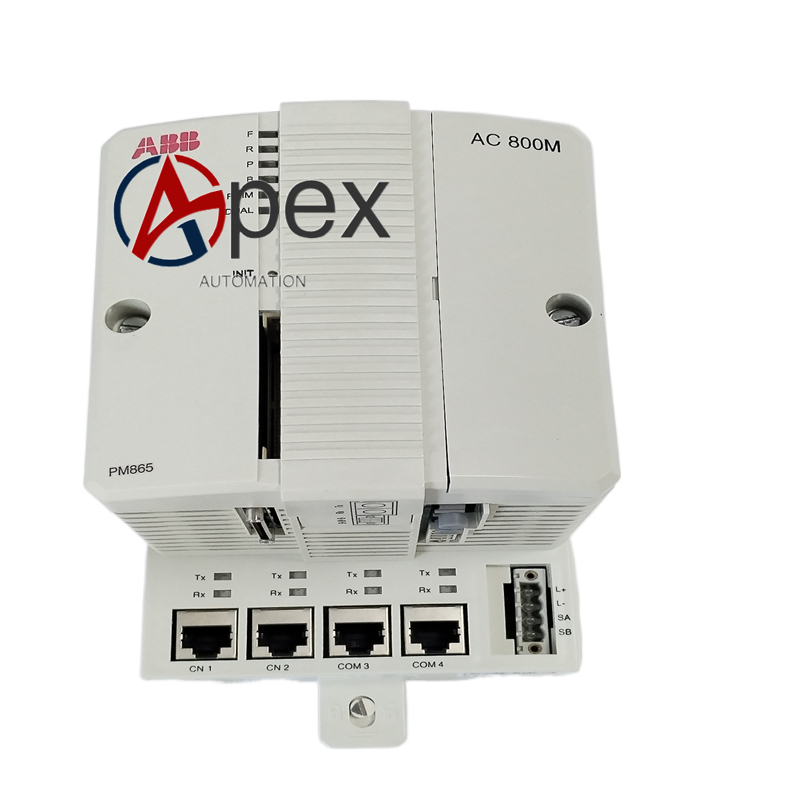
Application Scenarios Redundant SIL3 safety‑controller unit for petrochemical safety‑instrumented system, energy plant safety interlock cabinet and high‑risk chemical‑process automation. Designed for production sites where safety‑controller shutdown will cause serious safety hazard. Cooperates with S800 safety‑rated distributed I/O modules for safety‑signal acquisition and safety‑actuator driving. Integrates with System 800xA operator station for safety‑process monitoring, safety‑event historical recording and centralized safety‑alarm management. Applied to large‑scale continuous‑process industrial projects requiring SIL3 redundant safety‑controller architecture.
Installation Requirements Mount two dedicated base plates onto cabinet DIN rail or rack bracket, confirm mechanical locking is fully engaged for both positions. Wire 24 V DC power supply to each base‑plate detachable screw terminal block strictly following polarity marking. Install ModuleBus terminator and CEX‑Bus terminator at designated slot positions.




There are no reviews yet.