


Technical Specifications Encoder pulse signal input, differential signal processing. Auxiliary power 24 V DC, typical power consumption 4.5 W. Operating temperature ‑10 ℃ to +55 ℃, storage temperature ‑40 ℃ to +85 ℃, non‑condensing relative humidity 5%‑95%.
Functional Features Receives differential pulse signals from motor incremental encoder. Completes signal filtering, shaping and conversion. Transmits motor speed and position feedback data to drive main controller. On‑board LED indicates signal channel status. Built‑in hardware self‑diagnosis detects encoder signal loss and loop faults.
Application Scenarios Key spare‑part for ABB industrial AC drive systems. Used for motor speed closed‑loop control in metallurgy, lifting, papermaking and chemical industry equipment maintenance and spare‑part replacement.
Performance Parameters High‑precision pulse signal processing ensures motor speed detection accuracy. Strong anti‑interference capability for differential signal input. Self‑diagnosis rapidly identifies encoder signal interruption faults.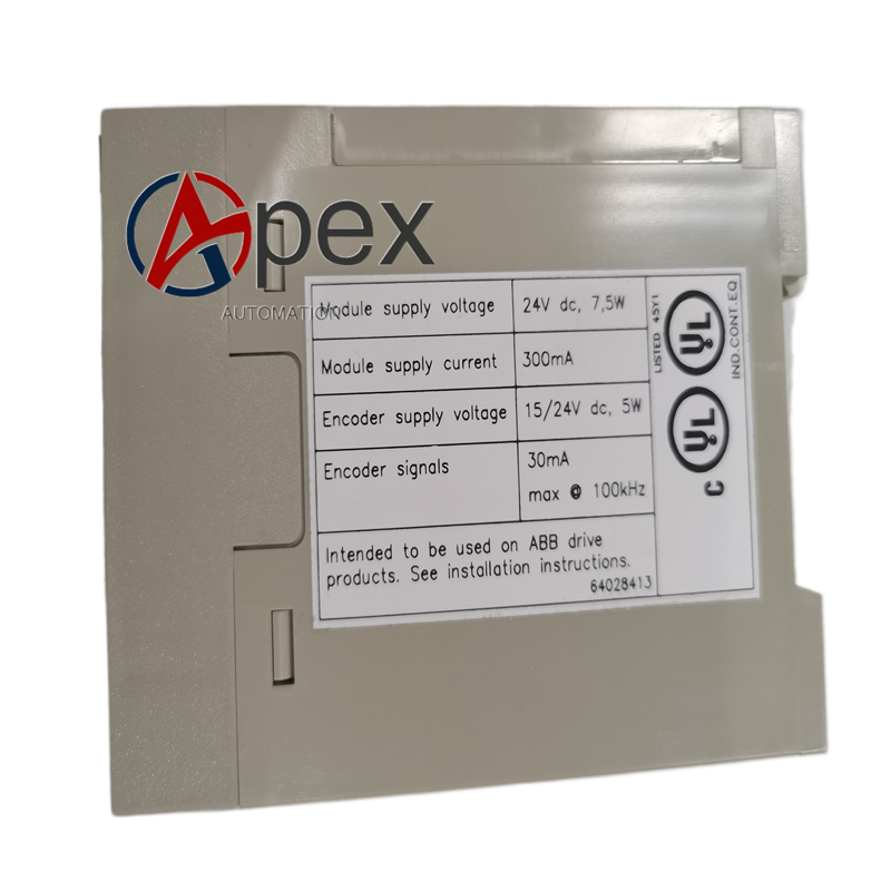
Material Composition Multilayer glass‑fiber epoxy printed circuit board. Differential signal receiving and conditioning components. Plastic module housing. Back‑plane plug‑in connectors and encoder signal wiring terminals.
Structural Characteristics Standard plug‑in module for drive unit rack. Front side equipped with signal wiring terminals and status LED indicators. Rear side fitted with back‑plane bus connector. Weight approximately 0.42 kilogram.
Working Principle After power‑on, module completes hardware self‑check. Differential pulse signals from motor encoder enter module. Signals go through filtering and shaping processing. Calculated motor speed and position data is sent to drive main controller via back‑plane bus. Diagnosis circuit continuously monitors encoder signal quality.
Installation Requirements Cut off drive unit main power and control power before replacement. Insert NTAC‑02 3BHL000511P0003 into designated slot and lock fixing latch. Complete encoder field wiring. Restore power supply and verify motor speed feedback function.
Usage Notes Use shielded cable for encoder signal wiring. Keep signal cable separate from high‑power power cable. Avoid mechanical stress on signal terminals. Complete speed feedback calibration after module replacement.




There are no reviews yet.