

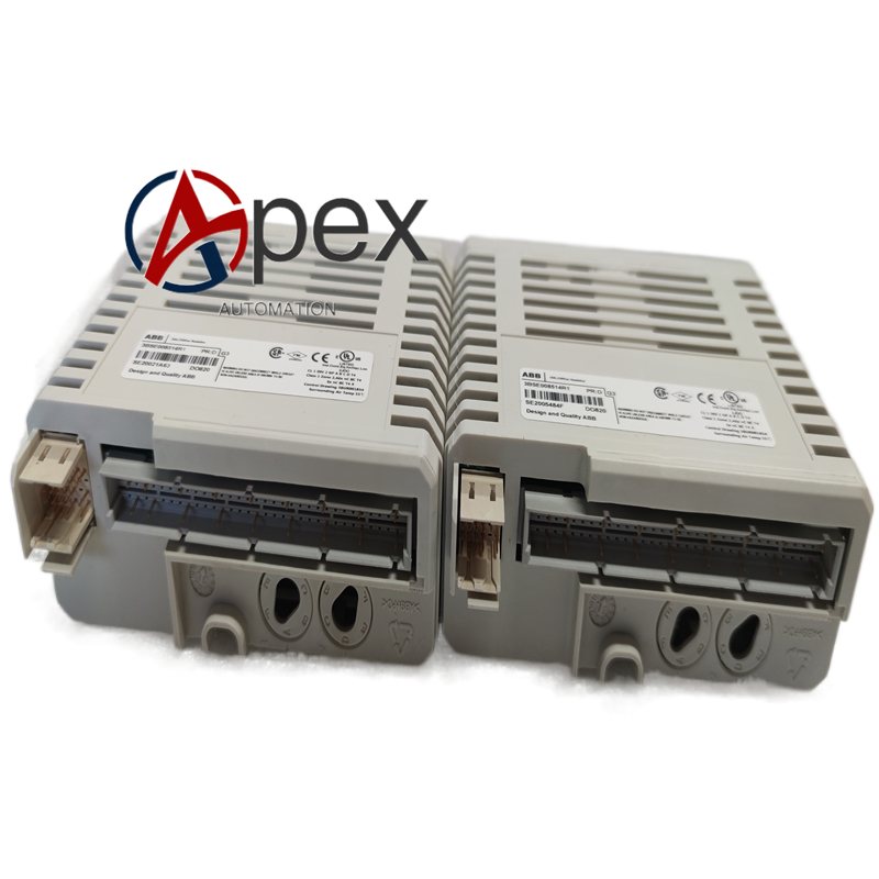
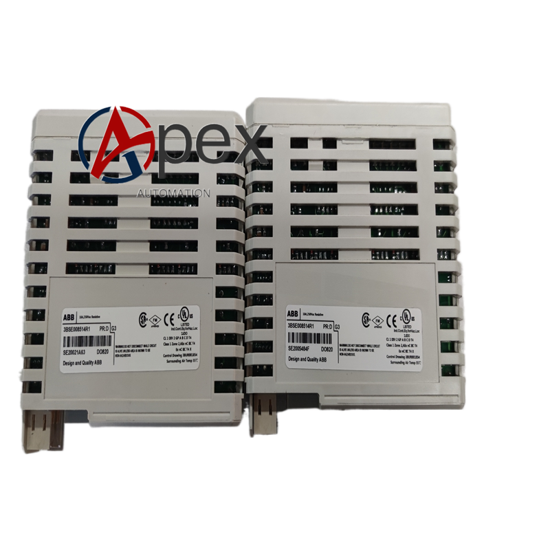

Technical Specifications Model: DO820, Part No. 3BSE008514R1 System Compatibility: ABB S800 I/O, AC800M Controller Output Channel Quantity: 16 channels Output Type: 24 V DC sinking transistor output Per‑channel Output Current: Maximum 0.5 A Isolation: Two groups of 8‑channel galvanic isolation Logic Power: From S800 rack backplane Field Power: External 24 V DC Mounting: DIN‑rail S800 rack plug‑in Operating Temperature: 0 ℃ to +55 ℃ Storage Temperature: ‑40 ℃ to +85 ℃ Relative Humidity: 5‑95 %, non‑condensing Protection Class: IP20 Certifications: CE, UL
Functional Features Sixteen‑channel sinking‑type 24 V DC transistor outputs realize high‑density discrete on‑off control. Two groups of 8‑channel galvanic isolation suppress inter‑group surge interference propagation. Per‑channel hardware over‑current and short‑circuit protection prevents module damage under field fault. Front‑panel LED indicators show real‑time output status for each channel. Built‑in self‑diagnosis function detects power‑supply abnormality, channel fault and communication failure. Supports hot‑swap operation under S800 system authorized maintenance conditions.
Application Scenarios S800 I/O DO820 3BSE008514R1 spare‑part replacement. Chemical industry, thermal power plant high‑density digital output control cabinet. On‑off control for large quantity of field‑side intermediate relays and small‑size solenoid valves.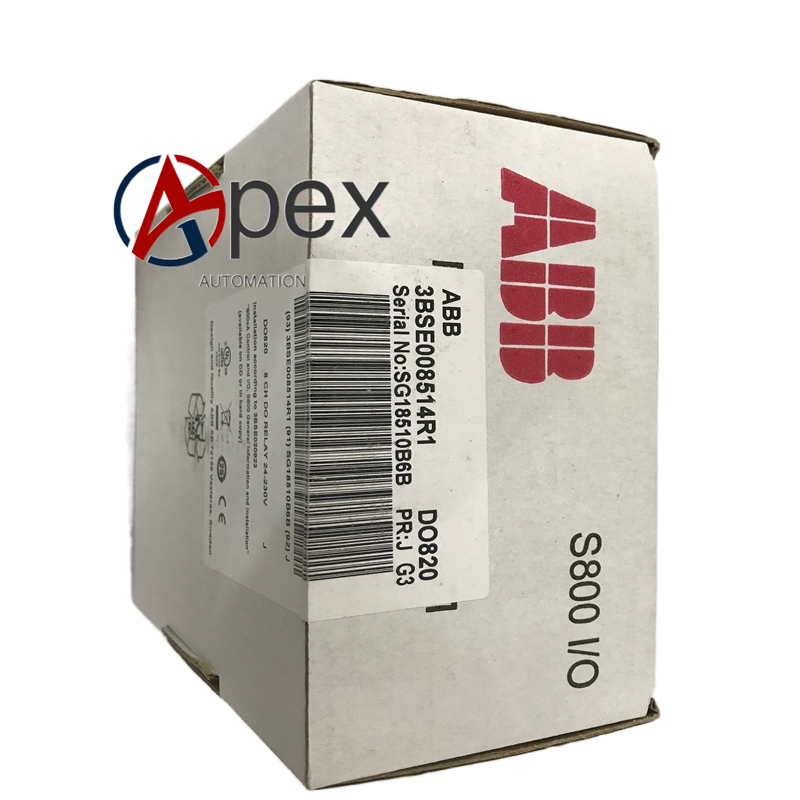
Installation Requirements Insert DO820 (3BSE008514R1) into S800 I/O rack target slot and lock side spring buckle. Connect external 24 V DC field power and field load cables to front‑side screw terminals, tighten terminals to specified torque. Implement protective earthing complying with S800 system grounding specification. Separate field output power cables from weak‑signal control cables inside control cabinet. Reserve ventilation heat‑dissipation space around module slot. Ambient operating temperature shall keep within 0 ℃ ~ +55 ℃ without condensation.
Usage Notes Per‑channel load current shall not exceed rated maximum value 0.5 A. Inductive loads shall install external free‑wheel suppression components. Do not apply voltage higher than 30 V DC to output terminals. Periodically inspect terminal fastening status and remove cabinet dust accumulation.




There are no reviews yet.