

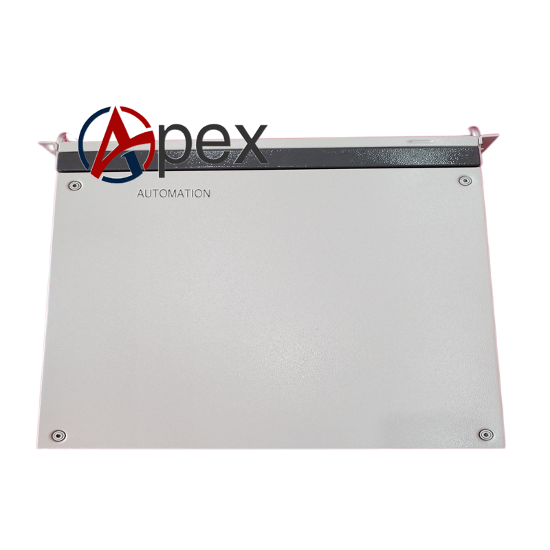

Technical Specifications Mounting Form: 19‑inch standard rack‑mount housing Installable Modules: Maximum 4 measurement modules Power Supply: 100‑240 V AC, 50/60 Hz Power Consumption: 220 W maximum Analog Output: 4‑20 mA, galvanic isolated Digital Interfaces: Ethernet TCP/IP, RS485 Modbus RTU Display: Integrated graphic touch‑screen operator panel Operating Temperature: +5 ℃ to +45 ℃ Storage Temperature: ‑20 ℃ to +70 ℃ Relative Humidity: 5‑95 %, non‑condensing Protection Class: IP20; IP54 with external junction box Dimensions: 483 mm × 177 mm × 412 mm (depth 597 mm with junction box) Certifications: CE, ATEX T4, IECEx
Functional Features Modular architecture supports flexible combination of multiple gas‑measurement modules. Built‑in touch‑screen for local parameter setting, calibration and data viewing. Automatic zero‑point and span calibration reduces manual maintenance workload. Comprehensive internal diagnostic functions monitor sample flow, temperature and module health status. Supports remote access, data logging and fault history recording. Provides both analog 4‑20 mA output and digital communication interfaces for upper‑level systems. Supports purge‑gas monitoring for hazardous‑gas measurement configurations. Hot‑swap replacement of measurement modules without shutting down the whole system.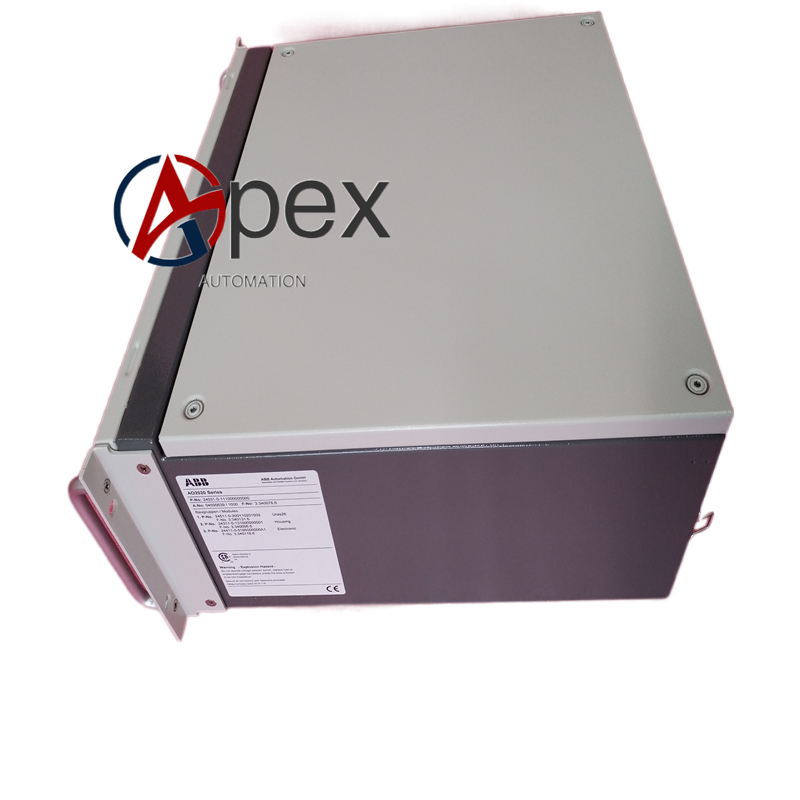
Application Scenarios Power‑plant flue‑gas emission continuous monitoring systems. Petrochemical and chemical process gas component online analysis. Steel‑mill furnace and coking‑plant gas monitoring. Waste‑incineration plant exhaust‑gas environmental‑compliance measurement. Fermentation and biogas production process‑gas analysis.
Usage Notes Do not introduce sample gas containing excessive dust, liquid droplets or corrosive components without pretreatment. Carry out regular zero‑point and span calibration according to operating‑manual requirements. Do not open optical‑module chambers in non‑maintenance conditions to avoid optical‑component contamination. Periodically inspect sample‑gas filter elements and replace aging consumable parts. For ATEX‑classified configurations, strictly follow hazardous‑area operation procedures. Avoid installation positions near strong vibration sources and heat sources.




There are no reviews yet.