

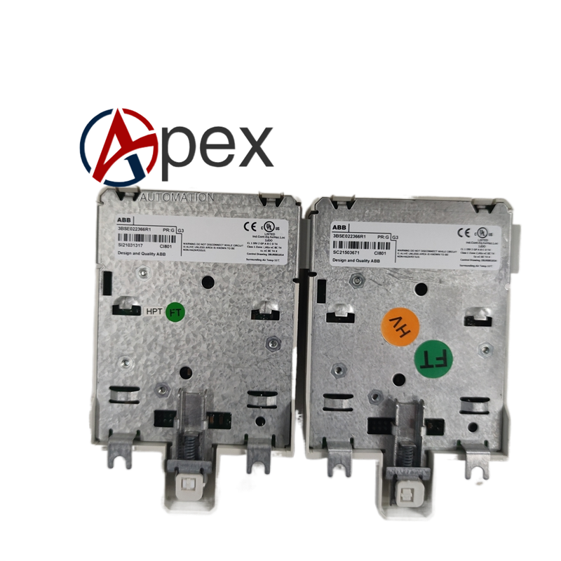

Technical Specifications Redundancy dedicated communication interface, back‑plane bus interface. Auxiliary power 24 V DC, typical power consumption 4.5 W. Operating temperature 0 ℃ to +60 ℃, storage temperature ‑40 ℃ to +85 ℃, non‑condensing relative humidity 5%‑95%. Conformal coated circuit board.
Functional Features Realizes high‑speed data synchronization between master and standby controller. Keeps consistency of logic variables, configuration parameters and fault status. Supports bumpless switch‑over between primary and standby controller. On‑board LED indicates synchronization link and module operating status. Built‑in hardware self‑diagnosis detects synchronization link failure and module hardware abnormality.
Application Scenarios Redundancy spare‑part for ABB redundant DCS controller rack. Applied in power plant and petrochemical important control loops which require high system availability.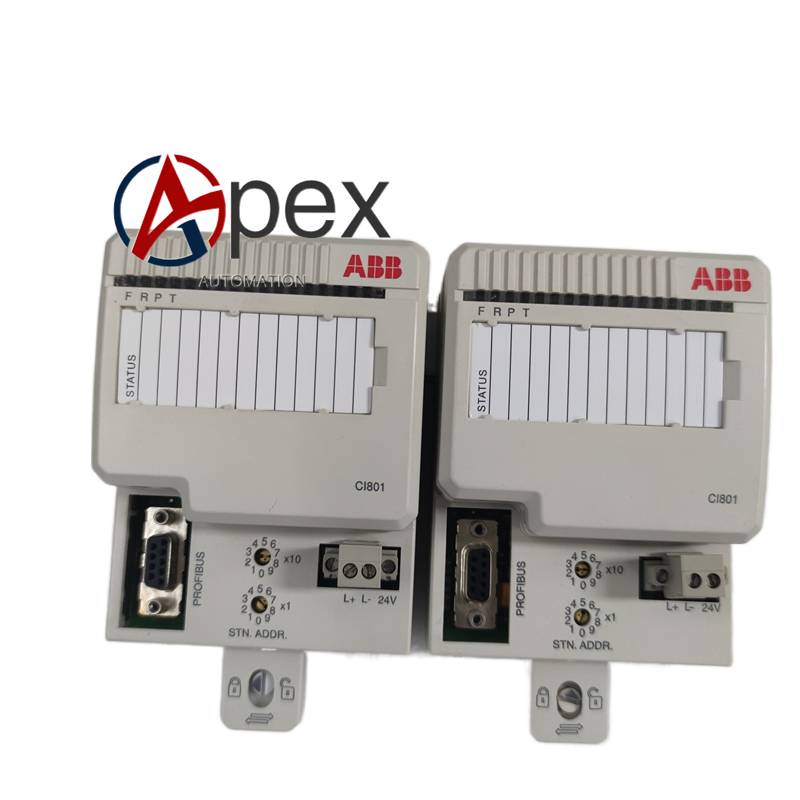
Performance Parameters High‑speed real‑time data synchronization performance. Fast bumpless switch‑over response when master controller fails. Accurate self‑diagnosis for synchronization channel faults.
Material Composition Flame‑retardant plastic module housing. Multilayer glass‑fiber epoxy printed circuit board. High‑speed data processing and signal isolation assemblies. Conformal protective coating. Back‑plane plug‑in connector and redundancy communication port.
Structural Characteristics Standard DCS plug‑in module structure. Front side equipped with communication port and status LED indicators. Rear side fitted with back‑plane bus connector. Weight approximately 0.40 kilogram.
Working Principle After power‑on, module completes hardware self‑test and synchronization initialization. It reads real‑time running data from local controller via back‑plane bus. High‑speed data exchange is carried out with opposite redundancy module through dedicated communication port. Data comparison and state updating are completed to keep master‑standby data consistent. Diagnosis circuit monitors synchronization link status continuously.
Installation Requirements Insert 3BSE022366R1 into designated redundancy slot of DCS controller rack and lock fixing latch. Connect dedicated redundancy communication cable between two redundant modules. Confirm back‑plane connector is fully engaged. Power on control system and verify master‑standby synchronization and switch‑over function.




There are no reviews yet.