

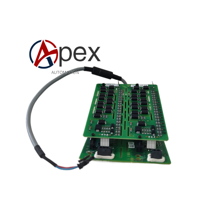
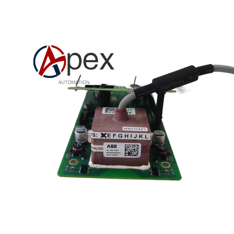
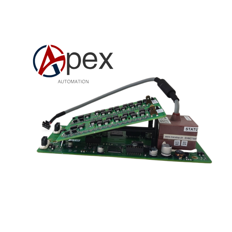

Technical Specifications Signal Interface:Multi‑channel fiber optic transmit‑receive ports Isolation:High‑voltage galvanic isolation between control side and power side Fault Monitoring:Over‑current, over‑temperature detection Operating Temperature:0 ℃ ~ +70 ℃ Mounting:Installed inside power unit module Connection:Fiber‑optic sockets, power‑device drive output terminals
Functional Features ‑ Convert optical trigger signals into drive pulses for power semiconductors ‑ High‑potential isolation between low‑voltage control circuit and high‑power circuit ‑ Real‑time fault detection for power unit ‑ Transmit fault alarm information back to main controller via optical fiber
Application Scenarios Power unit drive hardware for high‑power converter; spare‑part for power industry converter equipment overhaul.
Material Composition High‑voltage resistant multilayer PCB, optical transceiver assemblies, gate‑drive chips, high‑voltage passive components, drive terminals.
Structural Features Rectangular dedicated drive circuit board; fiber‑optic interfaces on board edge; power‑device output terminals; mounting holes for power‑unit internal installation.
Working Principle Optical trigger commands are received and converted into drive pulses to trigger power semiconductors. On‑board detection circuit monitors power‑device operating status. When fault occurs, fault signal is encoded and sent back to main controller through optical fiber.
Installation Requirements Fix board inside power‑unit module; connect optical fibers strictly following channel definition; guarantee ventilation and heat dissipation space.
Usage Notes Complete power‑off and capacitor discharge before maintenance; comply with ESD protection; avoid sharp bending of optical fiber cables.




There are no reviews yet.