

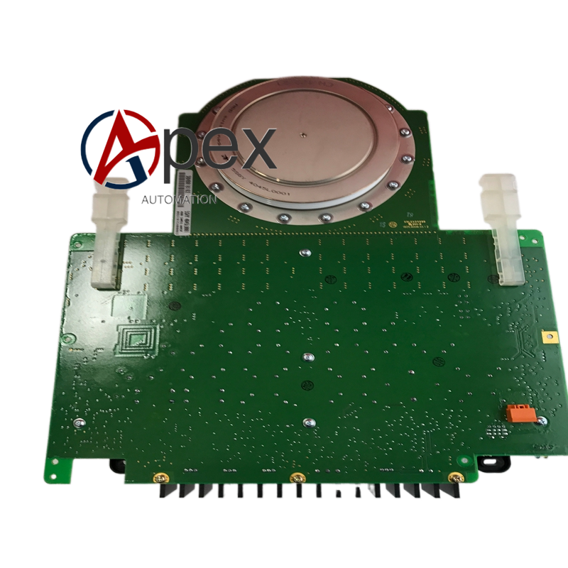

Technical Specifications Multi‑channel trigger signal output, back‑plane command input interface. Auxiliary power 24 V DC, typical power consumption 7.1 W. Operating temperature ‑10 ℃ to +55 ℃, storage temperature ‑40 ℃ to +85 ℃, non‑condensing relative humidity 5%‑95%. Conformal coated circuit board, isolation voltage 2300 V AC.
Functional Features Receives phase control commands from main control unit. Generates and shapes trigger pulse signals. Distributes driving pulses to each power semiconductor unit. On‑board LED reflects trigger channel operating status. Built‑in hardware self‑diagnosis detects pulse signal loss and circuit abnormality. Conformal coating improves environmental adaptability.
Application Scenarios Core spare‑part for ABB medium and high‑power rectifier and inverter units. Widely used in metallurgy, energy industry electrical equipment maintenance work.
Performance Parameters Accurate pulse phase and amplitude output meets power device triggering requirements. Stable signal output under industrial electromagnetic interference environment. Self‑diagnosis rapidly locates trigger channel hardware faults.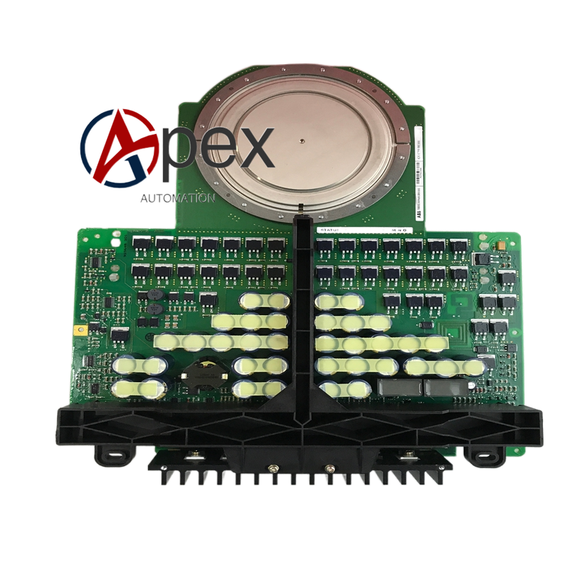
Material Composition Multilayer glass‑fiber epoxy printed circuit board. Pulse generation, shaping and driving assemblies. Conformal protective coating. Back‑plane plug‑in connectors and trigger pulse output terminals.
Structural Characteristics Plug‑in circuit board adapting to cabinet rack slot. Board edge equipped with back‑plane bus connector and pulse output wiring terminals. Reserved mechanical fixing holes. Weight approximately 0.68 kilogram.
Working Principle After power‑on, board completes hardware self‑initialization. Control commands are received from main controller via back‑plane bus. Internal circuit generates trigger pulses with corresponding phase angle. Processed pulse signals are distributed to power semiconductor units. Diagnosis circuit monitors real‑time working state of every output channel.
Installation Requirements Disconnect all high‑voltage power and auxiliary power of power cabinet before replacement. Insert 3BHB018162R0001 into corresponding slot and tighten fixing screws. Ensure back‑plane connector is fully locked. Restore power supply and complete trigger pulse function test.




There are no reviews yet.