

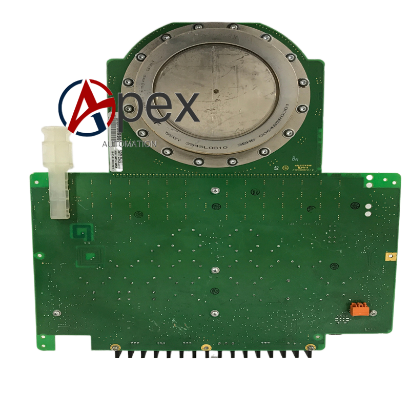

Technical Specifications Multi‑channel power signal distribution, fault feedback signal input interface. Auxiliary working power 24 V DC, typical power consumption 7.6 W. Operating temperature ‑10 ℃ to +55 ℃, storage temperature ‑40 ℃ to +85 ℃, non‑condensing relative humidity 5%‑95%. Conformal coated printed circuit board, isolation voltage 2400 V AC.
Functional Features Distributes stable auxiliary power to internal sub‑modules. Receives fault status feedback signals from power devices. Completes signal filtering and galvanic isolation for feedback loops. On‑board LED indicates board running and fault status. Built‑in hardware self‑diagnosis detects signal circuit open‑circuit and short‑circuit faults. Conformal coating provides moisture‑proof and dust‑proof protection.
Application Scenarios Replacement spare‑part for ABB high‑power inverter and excitation equipment. Applied in power plant, metallurgy heavy‑industry electrical equipment overhaul and spare‑part replacement.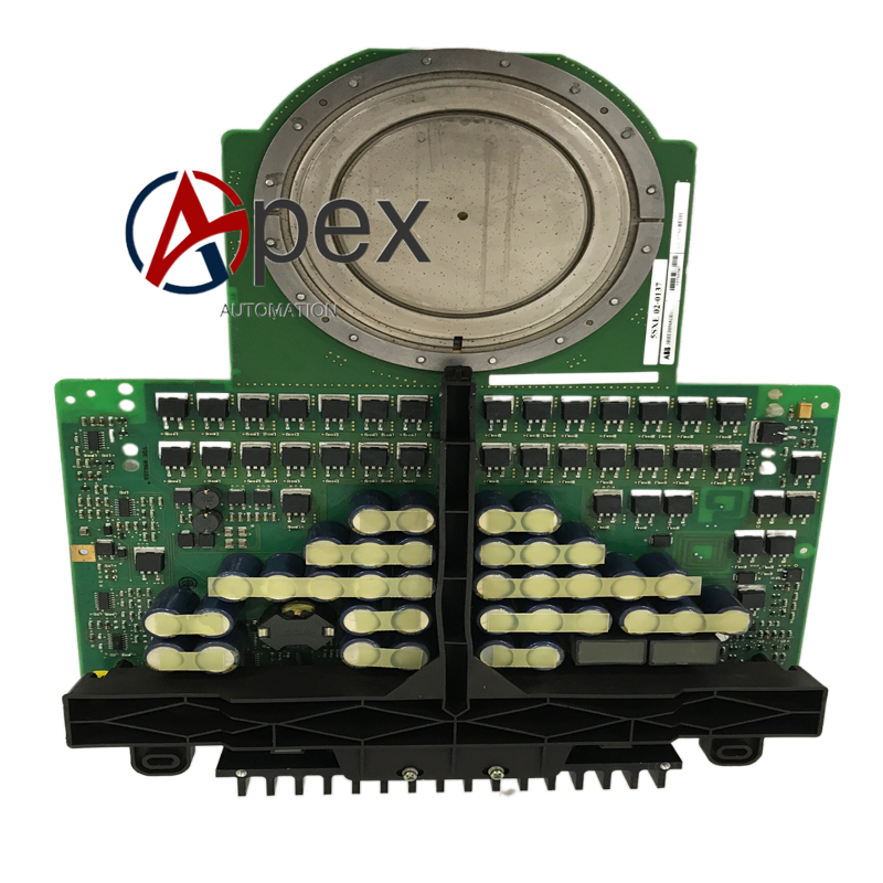
Performance Parameters Stable power distribution output under long‑time continuous operation. High‑speed fault signal transmission ensures timely system protection response. Galvanic isolation blocks high‑voltage interference from power side.
Material Composition Multilayer glass‑fiber epoxy printed circuit board. Power distribution assemblies, signal conditioning and optocoupler isolation components. Conformal protective coating. Back‑plane plug‑in connectors and power unit signal terminals.
Structural Characteristics Standard plug‑in circuit board matching power cabinet rack slot. Board edge equipped with back‑plane bus connector and external signal wiring terminals. Reserved mechanical fixing holes. Weight approximately 0.72 kilogram.
Working Principle After power‑on, the board completes hardware self‑check. Auxiliary power input is distributed to each internal sub‑circuit. Fault feedback signals from power semiconductor units enter the board, pass through filtering and isolation processing, and are transmitted to main control board via back‑plane bus. Diagnosis circuit continuously monitors power and signal loop working state.
Installation Requirements Cut off cabinet high‑voltage main power and auxiliary control power before replacement. Insert 3BHB013088R0001 into designated slot and tighten fixing screws. Confirm back‑plane connector is fully engaged.




There are no reviews yet.