

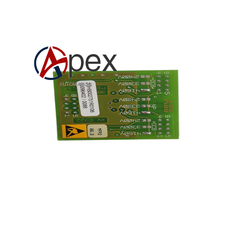

Technical Specifications Signal Interface: optical fiber communication between control unit and drive board Drive Object: high‑power power semiconductor devices Fault Detection: power unit over‑current, over‑temperature fault monitoring Galvanic Isolation: high‑potential isolation between low‑voltage control side and high‑voltage power side Operating Temperature: 0 ℃ to +70 ℃ Installation: fixed assembly inside high‑power converter power cabinet
Functional Features Receive optical fiber trigger command and generate power semiconductor drive pulse. High‑potential galvanic isolation separates low‑voltage control circuit and high‑voltage power circuit. Real‑time detection for power unit abnormal fault condition. Fault status upload to main controller by optical fiber channel.
Application Scenarios Gate drive hardware for large‑capacity power converter in heavy‑industry site. Power unit drive board for power plant excitation and frequency conversion equipment. Spare replacement component for high‑power converter cabinet overhaul maintenance.
Performance Parameters Fast drive pulse response ensures high‑power device real‑time control. High‑voltage isolation performance satisfies power‑electronic equipment safety standard. Rapid fault detection response speed for power unit protection action.
Material Composition High‑voltage‑resistant special printed circuit board. Optical‑fiber receiving‑transmitting components. Gate drive chip and high‑voltage isolation components. High‑voltage‑resistant passive electronic parts.
Structural Features Rectangular dedicated drive circuit board assembly. Optical fiber interfaces arranged on board edge. Multiple power drive output terminals. Fixing hole positions for installation inside converter cabinet.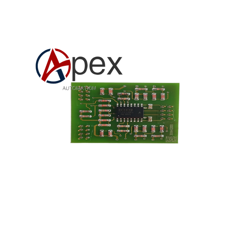
Working Principle Control command transmits from main controller to this drive board through optical fiber. After signal conversion, drive pulse outputs to power semiconductor device. Board‑level detection circuit monitors power unit working state. Once fault is detected, fault message is sent back to main controller via optical fiber.
Installation Requirements Fasten drive board to designated mounting position inside converter cabinet. Complete optical‑fiber jumper connection according to signal definition. Check fastening status of drive output terminals. Guarantee sufficient ventilation heat‑dissipation space around board.
Usage Notes Fully execute high‑voltage power‑off and capacitor discharge procedure before maintenance operation. Do not bend optical‑fiber cable with too small bending radius. Observe strict electrostatic protection requirement when handling circuit board.




There are no reviews yet.