

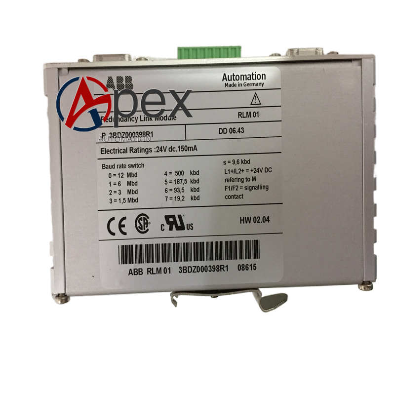

Technical Specifications Multi‑channel isolated digital output. Auxiliary logic power 24 V DC, typical power consumption 3.9 W. Operating temperature 0 ℃ to +60 ℃, storage temperature ‑40 ℃ to +85 ℃, non‑condensing relative humidity 5%‑95%. Galvanic isolation between internal logic circuit and field output circuit.
Functional Features Provides multiple independent digital output channels. Realizes galvanic isolation between control logic side and field load side. Each channel equipped with LED status indicator. Built‑in hardware over‑current protection for output channels. Supports hardware self‑diagnosis for output circuit abnormality.
Application Scenarios Logic output spare‑part for ABB DCS and PLC control systems. Used in chemical, power and manufacturing automation projects to drive field‑side switching equipment.
Performance Parameters Stable long‑term switching output performance. Galvanic isolation blocks field‑side interference from entering control rack. Self‑diagnosis rapidly detects output channel overload and short‑circuit faults.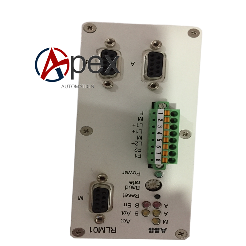
Material Composition Flame‑retardant plastic module housing. Multilayer glass‑fiber epoxy printed circuit board. Output driving and isolation assemblies. Back‑plane plug‑in connector and field wiring screw terminals.
Structural Characteristics Standard plug‑in module structure for control rack. Front side equipped with field wiring terminals and channel status LED indicators. Rear side fitted with back‑plane bus connector. Weight approximately 0.33 kilogram.
Working Principle Main controller sends logic output command via back‑plane bus. Internal driving circuit acts according to command. Isolated switching signal is output to field‑connected load equipment. LED indicator synchronously reflects each channel output state. Diagnosis circuit monitors output channel working condition continuously.
Installation Requirements Insert 3BDZ000398R1 into target slot of control rack and lock fixing latch. Complete field‑side load wiring on front‑end screw terminals. Confirm back‑plane connector is fully engaged. Power on control system and carry out channel output function test.
Usage Notes Do not exceed rated voltage and current parameter of output channel. Prevent over‑load operation.




There are no reviews yet.