

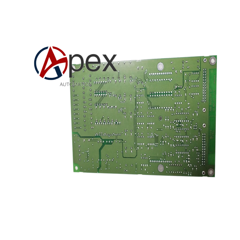

Technical Specifications Working Environment: inside variable‑frequency drive power cabinet Signal Isolation: galvanic isolation between control side and power side Operating Temperature: 0 ℃ to +70 ℃ Form: plug‑in circuit board for drive rack Connection: internal pin connectors and flat cable interfaces
Functional Features Sampling and transmission for voltage and current feedback signals of power unit. Isolated drive signal transmission for power semiconductor components. Fault signal feedback from power unit to main control logic. Hardware over‑temperature and over‑current auxiliary detection function.
Application Scenarios Internal power interface hardware for high‑power industrial frequency converter. Signal transfer board for large motor drive unit in heavy‑industry site. Replacement spare part for ABB drive cabinet maintenance work.
Performance Parameters Isolation performance meets high‑power drive safety requirement. Low‑delay signal transmission ensures real‑time drive control. Stable operation under drive cabinet high‑temperature working condition.
Material Composition High‑voltage‑resistant multilayer printed circuit board. Isolation optocoupler and signal processing chips. High‑voltage resistant passive components. Flat‑cable connectors and pin sockets.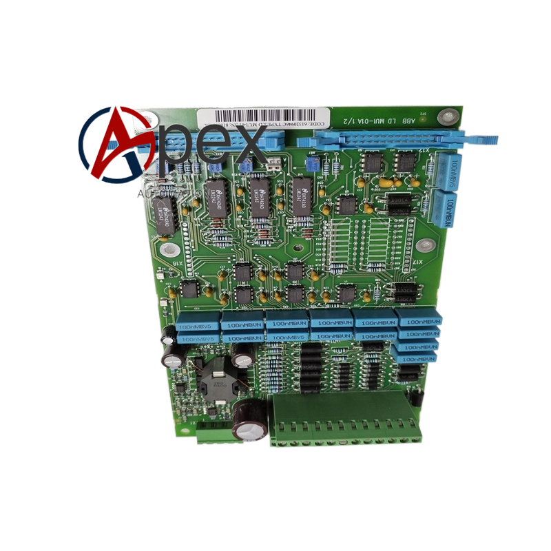
Structural Features Rectangular plug‑in circuit board assembly. Multiple flat‑cable and pin connectors on board edge. Mounting hole positions for fixing inside drive cabinet.
Working Principle Main control board sends drive control signal to this board. After galvanic isolation processing, signal outputs to power semiconductor unit. Voltage, current and fault status signals collected from power unit feed back to main control board through this interface board.
Installation Requirements Fix circuit board to designated installation position inside inverter cabinet. Complete flat‑cable and pin connector insertion, ensure full locking. Keep safe clearance between board and high‑voltage power components.
Usage Notes Strictly execute high‑voltage power‑off and discharge procedure before disassembly. Observe anti‑static measure when touching circuit board. Check all cable connectors fastening status after installation.




There are no reviews yet.