

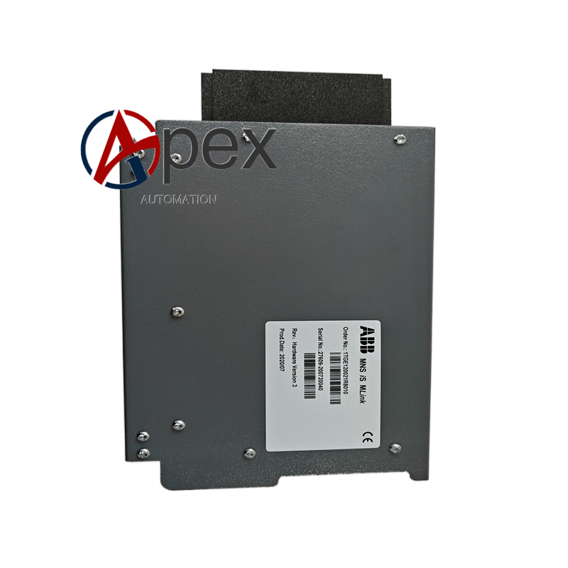
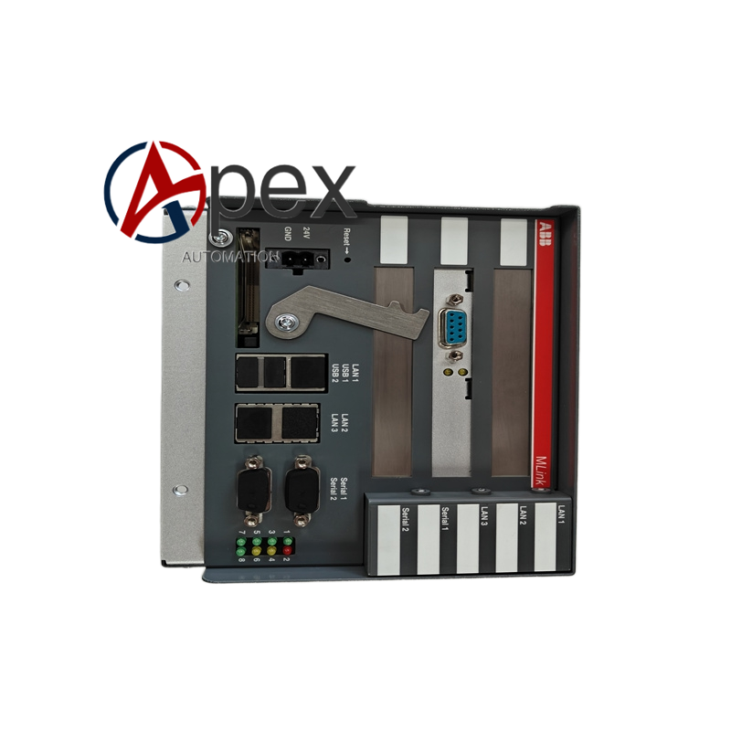

Technical Specifications Rated Insulation Voltage: 690 VAC Rated Operational Current: 32 A Contact Poles: multi‑pole synchronous contact groups Mounting Type: cabinet front‑panel cut‑out mounting Front‑panel Protection Class: IP65 Operation Mode: rotary manual handle Operating Temperature: ‑25 ℃ to +70 ℃
Functional Features Multi‑pole synchronous make‑and‑break for power or control loops. Disconnector function provides safety isolation gap for maintenance work. Mechanical position marking shows real contact working status. High‑protection front‑panel structure adapts dusty industrial workshop environment. Compact stacked contact chamber saves internal installation space.
Application Scenarios Maintenance isolation switch for auxiliary power circuit inside industrial control cabinet. Power cut‑off switch for pump and fan local operation box. Manual isolation device for machine‑tool control panel power supply. Disconnecting component for small‑size on‑site distribution auxiliary circuit.
Performance Parameters All‑pole contacts complete switching action synchronously. Isolation gap meets low‑voltage disconnector safety specification. Contact conductivity keeps stable under continuous rated load current.
Material Composition Flame‑retardant insulating housing. Metal rotary shaft and cam transmission mechanical assembly. Silver‑alloy multi‑pole contact components. Front‑panel sealing rubber ring. Rear‑side screw terminal blocks.
Structural Features Front‑panel mounting fixing flange structure. Rotary operating handle with position symbol mark. Stack‑type multi‑pole contact chambers inside housing. Rear‑facing terminals for incoming and outgoing circuit wiring.
Working Principle Manual rotation of front‑panel handle drives internal cam shaft. Cam profile pushes multi‑pole contact groups to close or open synchronously. Open‑position creates safe electrical isolation gap between upstream power source and downstream load circuit.
Installation Requirements Pass switch body through reserved cut‑out hole on cabinet front panel. Fasten mounting flange tightly against cabinet panel surface. Complete upstream and downstream wiring at rear‑side screw terminals.
Usage Notes This device is not designed for breaking short‑circuit fault current. Verify handle position indication is consistent with actual contact status during commissioning. Avoid mechanical damage to front‑panel sealing rubber ring.




There are no reviews yet.