

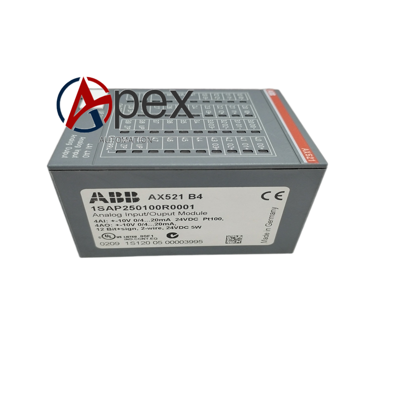

Technical Specifications 8‑channel analog input, supports 4‑20 mA and 0‑10 V signal types. Auxiliary power 24 V DC, typical power consumption 3.8 W. Operating temperature 0 ℃ to +60 ℃, storage temperature ‑40 ℃ to +85 ℃, non‑condensing relative humidity 5%‑95%. Galvanic isolation between channels and back‑plane bus.
Functional Features Acquires multi‑channel standard analog field signals. Completes analog‑to‑digital conversion. Transmits digital process data to PLC CPU via back‑plane bus. Each channel equipped with status LED indicator. Supports hardware self‑diagnosis for signal loop breakage and short‑circuit faults.
Application Scenarios Industrial automation projects for water treatment, manufacturing, chemical and building automation. Used for collecting pressure, flow, temperature and liquid level transmitter signals.
Performance Parameters High‑precision analog‑digital conversion guarantees measurement accuracy. Galvanic isolation reduces field‑side interference impact. Self‑diagnosis provides clear fault information for field signal loops.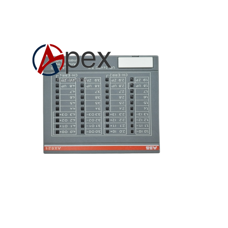
Material Composition Flame‑retardant plastic module housing. Multilayer glass‑fiber epoxy printed circuit board. Signal conditioning and A/D conversion components. Back‑plane plug‑in connector and field wiring screw terminals.
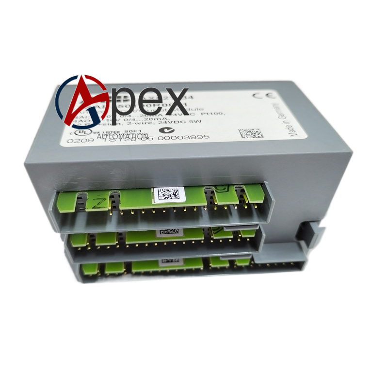
Structural Characteristics Standard PLC plug‑in module structure. Front panel arranges channel status LED and field wiring terminals. Rear side equipped with back‑plane bus connector. Weight approximately 0.34 kilogram.
Working Principle Field analog signals enter module through front‑end terminals. Signals pass through filtering and conditioning circuit. Analog‑digital conversion chip converts analog quantity into digital data. Digital data is transmitted to PLC main CPU via back‑plane bus. Diagnosis circuit monitors signal loop condition continuously.
Installation Requirements Insert 1SAP250100R0001 into designated slot of PLC rack and lock fixing latch. Complete field sensor signal wiring on front‑end terminals. Confirm back‑plane connector is fully engaged. Power on PLC system and perform channel signal acquisition test.
Usage Notes Use shielded cable for analog signal wiring. Separate signal cable from high‑voltage power cable. Check terminal tightening torque in regular maintenance. Avoid condensation and corrosive‑gas operating environment.




There are no reviews yet.