

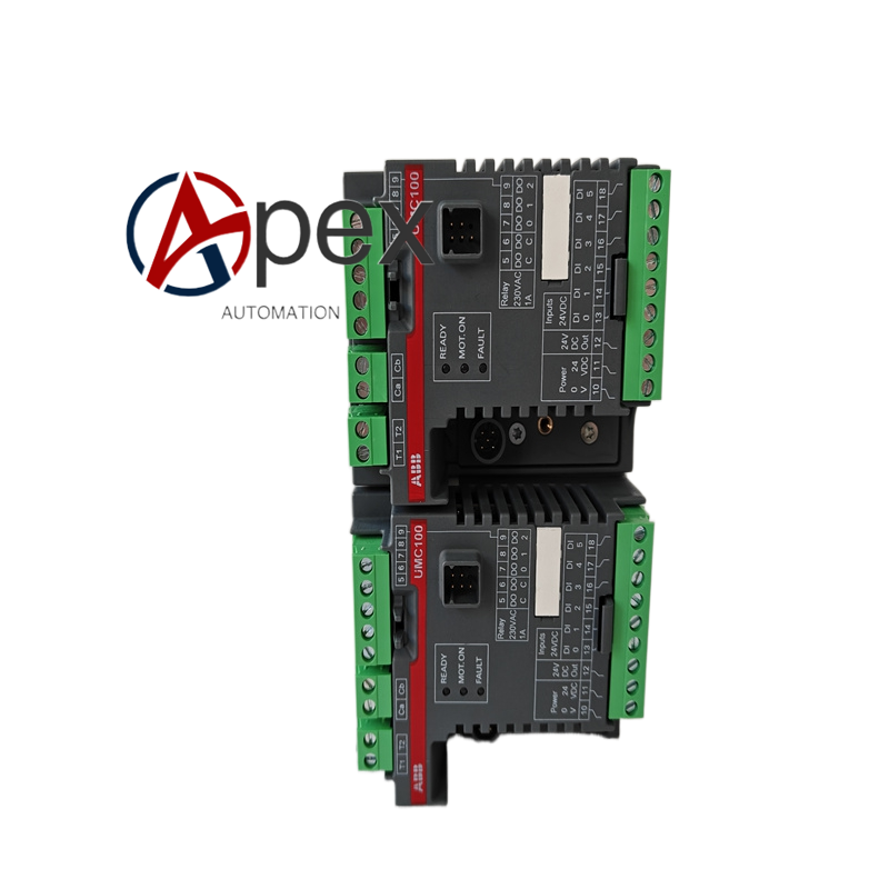
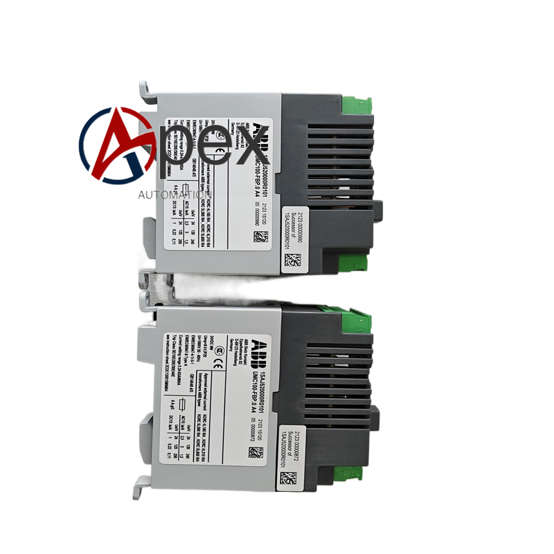
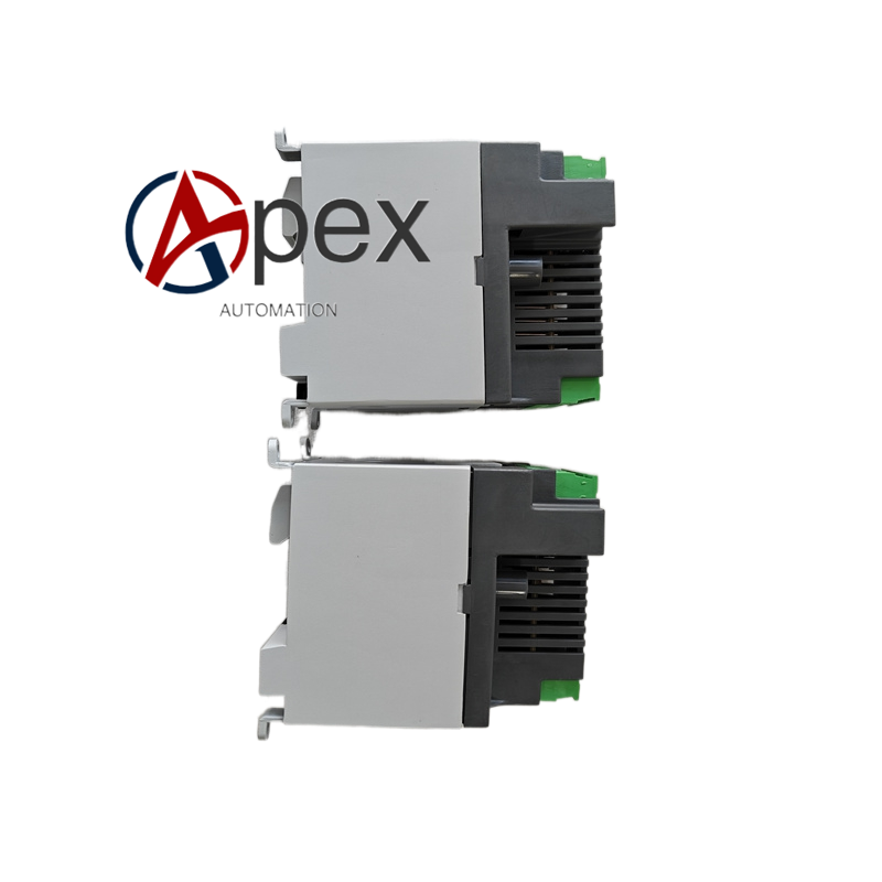

Technical Specifications Supply Voltage: 24 VDC nominal Power Consumption: 9 W Direct Current Setting Range: 0.24 A to 63 A; expand to 800 A with external current transformer Trip Class: 5E,10E,20E,30E,40E configurable Rated Insulation Voltage Ui: 1000 V Impulse Withstand Voltage Uimp: 8 kV Mounting Method: 35 mm DIN‑rail mounting Protection Class: IP20 Operating Temperature: ‑20 ℃ to +70 ℃ Compliance Standard: IEC 60947‑4‑1, IEC 60947‑8
Functional Features Comprehensive motor protection including overload, phase unbalance, phase loss and short‑circuit. Real‑time monitoring for motor operating current and running status. Fieldbus communication interface for remote parameter setting and status uploading. Multiple configurable trip classes adapt different motor thermal characteristic. DIN‑rail quick installation structure.
Application Scenarios Low‑voltage motor protection and control for petrochemical process plant. Motor control unit for water treatment and waste‑water processing system. Fan, pump and conveyor motor protection inside power plant auxiliary workshop. Manufacturing workshop automated production line motor control cabinet.
Performance Parameters Protection trip accuracy conforms IEC standard for low‑voltage motor protection. Accurate motor thermal memory calculation for repeated start‑stop operating condition. Stable communication data exchange with upper‑level control system.
Material Composition Flame‑retardant engineering plastic housing. Industrial control printed circuit board. Current sampling and protection trigger components. DIN‑rail metal spring clip assembly.
Structural Features Compact DIN‑rail modular housing structure. Front‑panel operating indicator LED group. Screw terminal blocks for power and signal wiring. Built‑in spring clip for 35 mm DIN‑rail fastening.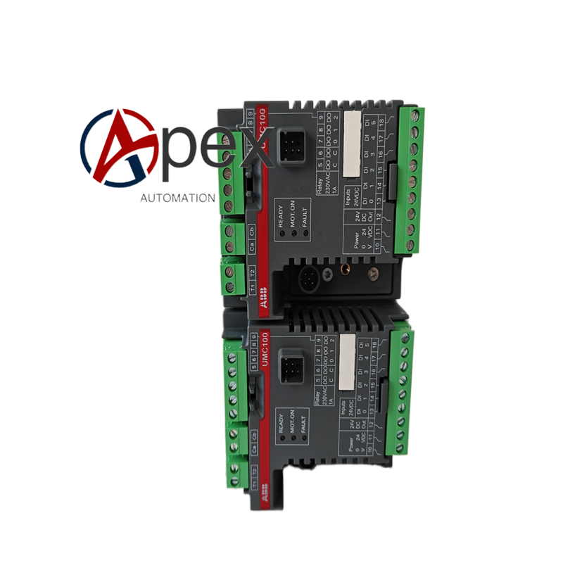
Working Principle Controller samples three‑phase motor operating current continuously. Internal microprocessor calculates motor thermal accumulation value. When operating parameter exceeds protection threshold, controller triggers protection trip action. Operating data and fault information upload to upper host system through fieldbus interface.
Installation Requirements Fasten device onto standard 35 mm DIN‑rail inside control cabinet. Complete main‑circuit and control‑circuit wiring according to wiring diagram. Reserve clearance around device for heat dissipation.
Usage Notes Set protection trip parameter matching actual motor nameplate data. Confirm wiring polarity of 24 VDC control power supply. Do not operate under ambient temperature exceeding rated range.




There are no reviews yet.