

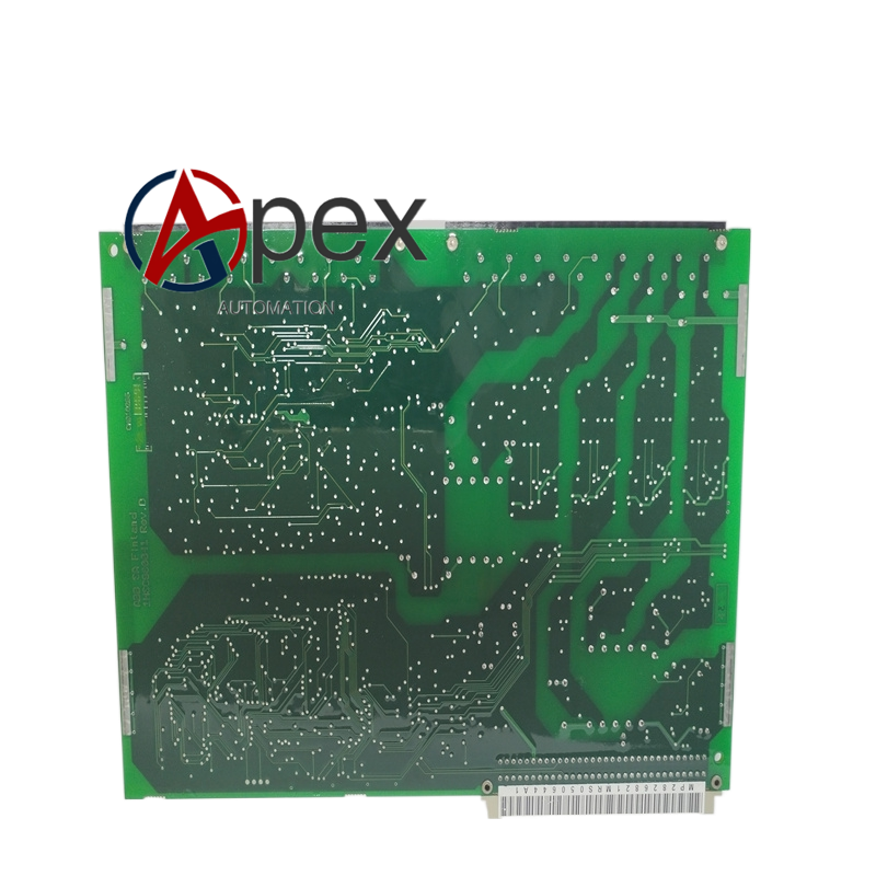

Technical Specifications Signal Channel Quantity: multi‑channel signal conditioning and interface loop Withstand Isolation Voltage: 2000 VAC between field side and internal circuit Operating Temperature: ‑25 ℃ to +70 ℃ Signal Processing: surge suppression and RC signal filtering Connection Mode: plug‑in backplane connector and field screw terminal block Protection Grade: IP20 for module assembly
Functional Features Signal conditioning for analog and binary signals coming from field secondary circuit. Built‑in surge suppression components restrain transient over‑voltage interference. Galvanic isolation between field secondary circuit and protection main circuit. Filter circuit eliminates high‑frequency noise interference on signal lines. Modular plug‑in structure convenient for on‑site maintenance replacement.
Application Scenarios Signal interface for substation line and transformer protection relays. Secondary circuit signal matching for power plant generator protection devices. Hardware interface for smart grid substation automation protection cabinet.
Performance Parameters Signal attenuation keeps within allowable range for protection sampling requirement. Surge suppression components absorb transient voltage impulse from field wiring. Isolation circuit block interference cross‑transmission between channels.
Material Composition Industrial anti‑interference printed circuit board. Surge absorption and optocoupler isolation components. Flame‑retardant plastic terminal blocks. Gold‑plated plug‑in contact parts.
Structural Features Plug‑in board assembly inside protection relay chassis. Screw terminal blocks for external secondary field wiring. Back‑end multi‑pin connector connects with protection main board. Fixing buckle for positioning inside device chassis.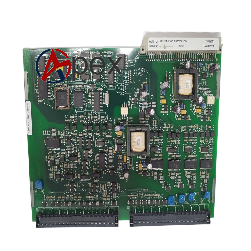
Working Principle Field secondary signal enters interface board through screw terminals. Surge suppression and filter circuit process incoming signal. Isolation circuit achieves electrical separation, conditioned signal transmits to protection main processing board via back‑end connector.
Installation Requirements Insert interface board into designated inner slot of protection relay chassis. Lock positioning buckle to guarantee reliable connector contact. Complete secondary wiring strictly follow terminal definition drawing.
Usage Notes Cut off secondary circuit power before disassembly and wiring work. Do not change original components on interface board. Check terminal wiring tightness in periodic maintenance work.




There are no reviews yet.