

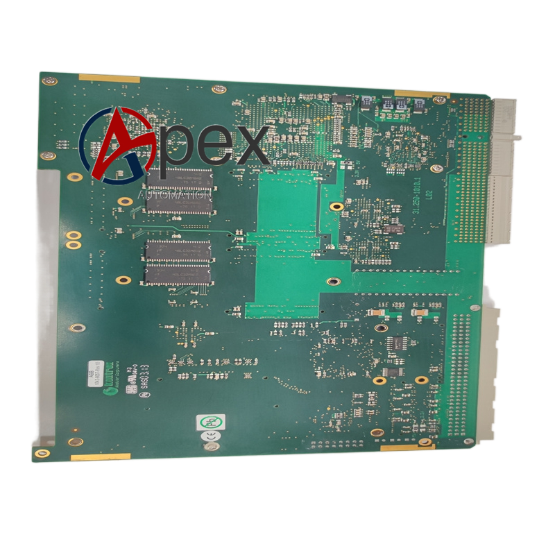

Technical Specifications System Bus Interface: proprietary high‑speed internal backplane bus Data Processing Type: floating‑point arithmetic, integer operation, boolean logic calculation Data Format Support: 32‑bit float, 16‑bit and 32‑bit integer, boolean value Operating Temperature: -20 ℃ to +60 ℃ Storage Temperature: -40 ℃ to +85 ℃ Module Physical Form: rack‑mount plug‑in board assembly Power Supply: supplied by system rack backplane
Functional Features High‑speed parallel numeric calculation for power protection algorithm. Multi‑format data receiving and processing from other system modules. Low‑delay computation output for protection action judgment. Real‑time data interaction through dedicated internal high‑speed bus. Built‑in self‑diagnosis function for hardware operating state.
Application Scenarios Numerical calculation unit for substation relay protection device. Real‑time signal processing for transformer and line protection system. Smart grid protection control cabinet internal computing hardware. Power plant generator set protection logic operation platform.
Performance Parameters Deterministic short computation cycle for protection algorithm. Stable data transmission throughput on internal system bus. Hardware self‑diagnosis can accurately locate module internal fault.
Material Composition High‑speed signal multilayer printed circuit board. Industrial grade high‑performance processing chip. Anti‑vibration gold‑plated backplane connectors. Metal heat‑dissipation structural components.
Structural Features Standard rack‑mount plug‑in board form factor. Back‑end gold‑plated contact pins connect with system backplane bus. Front‑panel status LED indicators for hardware running condition. Pull‑out mechanical handle for module maintenance replacement.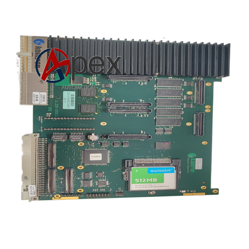
Working Principle Module receives sampling data and logic signals transmitted by system backplane bus. Internal processing chip executes predefined protection arithmetic algorithm. Calculation result returns to other functional modules through backplane bus to complete protection judgment and action command output. On‑board diagnosis circuit monitors hardware running status continuously.
Installation Requirements Insert module into corresponding slot of protection system rack. Ensure full engagement of backplane connector pins. Reserve cabinet heat dissipation space for module continuous operation.
Usage Notes Module hot‑swap shall follow official system operating procedure. No modification of module hardware circuit is allowed. Check front‑panel LED status indicator during regular inspection.




There are no reviews yet.