

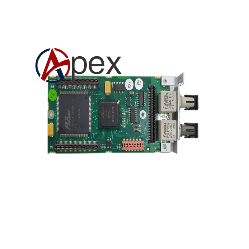
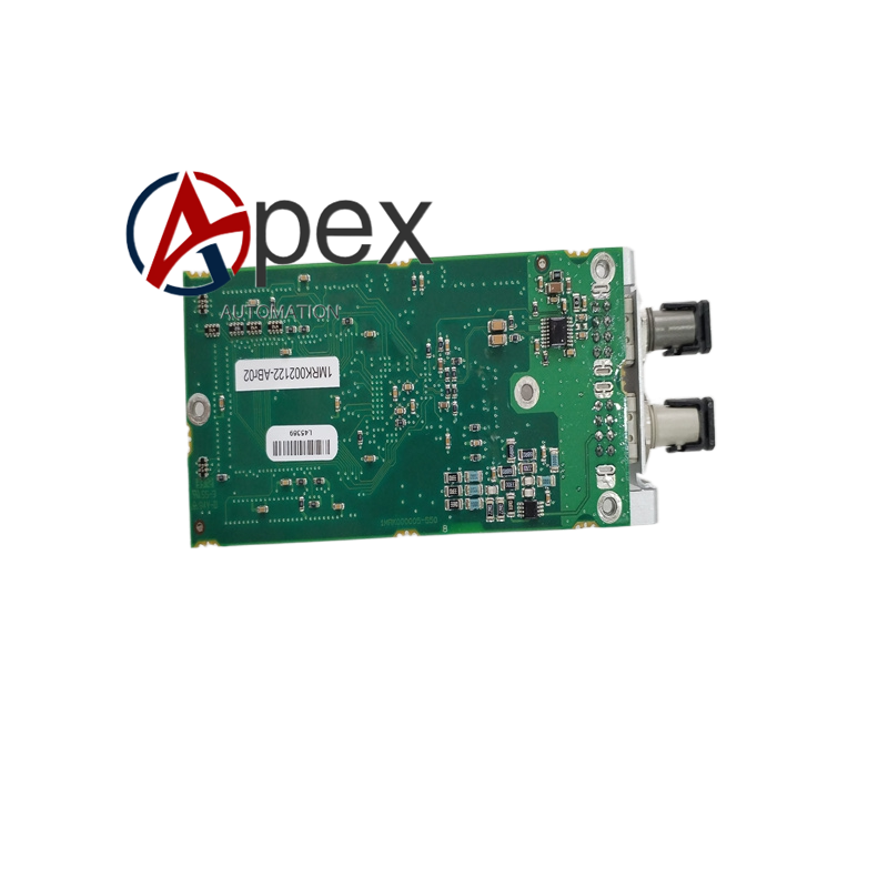

Technical Specifications Output Contact Form: single‑pole normally open electromechanical relay contact Resistive Load Rating: 25 A at 250 VAC, 25 A at 30 VDC Control Circuit Supply: 24 VDC logic level Galvanic Isolation Voltage: 2500 V between control side and load side Operating Temperature: -25 ℃ to +70 ℃ Mechanical Life: large number of relay operation cycles for protection application Module Form: plug‑in board for protection relay chassis
Functional Features Electromechanical relay contact output for high‑power field load driving. Complete galvanic isolation separates internal protection logic and external field circuit. Support switching action for breaker trip command and alarm signal output. Plug‑in modular structure for convenient replacement and maintenance.
Application Scenarios REF541, REF543, REF545 feeder and transformer protection relay extension output. Circuit breaker trip and close command output in power substation protection system. Protection system fault alarm signal driving for on‑site indicator light and horn. Secondary equipment interlock signal switching for power grid automation system.
Performance Parameters Contact switching capacity meets resistive and inductive industrial load requirement. Isolation performance satisfies substation secondary circuit safety standard. Stable contact action performance under long‑term frequent operation.
Material Composition Industrial grade printed circuit board. High‑capacity electromechanical relay components. High‑voltage isolation insulation parts. Gold‑plated plug‑in contact terminals.
Structural Features Plug‑in board module matching protection relay chassis slot. External screw terminals for field load wiring. Built‑in positioning buckle for reliable insertion location.
Working Principle Protection relay internal logic sends 24 VDC control signal to module. Control signal drives relay coil to actuate mechanical contact closing or opening. Galvanic isolation barrier achieves electrical separation between relay coil control circuit and external load contact circuit.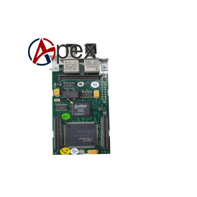
Installation Requirements Insert module into designated expansion slot of REF54 series protection relay. Lock module buckle to guarantee stable plug‑in contact. Complete field load wiring according to terminal marking definition.
Usage Notes Load current shall not exceed rated contact switching capacity. Disconnect high‑voltage secondary circuit power before module plug‑in or removal. Carry out contact state inspection during periodic protection device maintenance.




There are no reviews yet.