

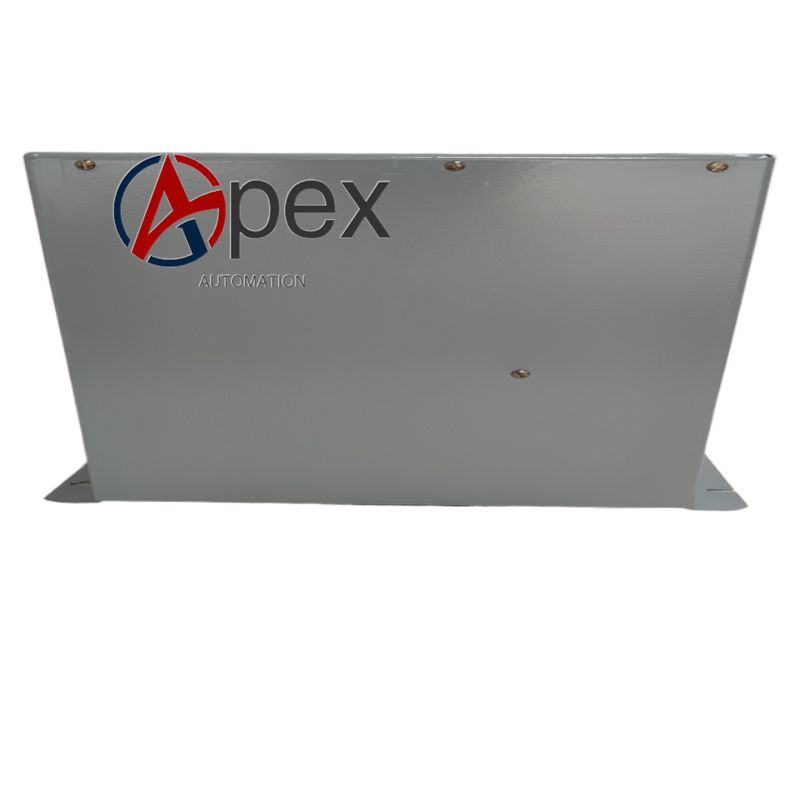

Technical Specifications Multi‑rail power‑signal monitoring interfaces, internal system bus connector, auxiliary DC control power supply. Operating temperature 0 ℃ to +60 ℃, storage temperature ‑40 ℃ to +85 ℃, relative humidity 5%‑95% non‑condensing. Conformal coating PCB anti‑corrosion treatment. Chassis screw‑fix mounting structure.
Functional Features Real‑time monitors voltage status of each output power rail from system power unit. Implements system power‑on and power‑off sequence control logic. Detects over‑voltage, under‑voltage and power‑loss fault events. Outputs power‑good status signal to main control processor. Supports power‑supply‑related fault self‑diagnosis and fault‑code reporting.
Application Scenarios Spare replacement power control board for GE DS3820 industrial control systems, used for power‑industry and heavy‑manufacturing automation equipment maintenance work.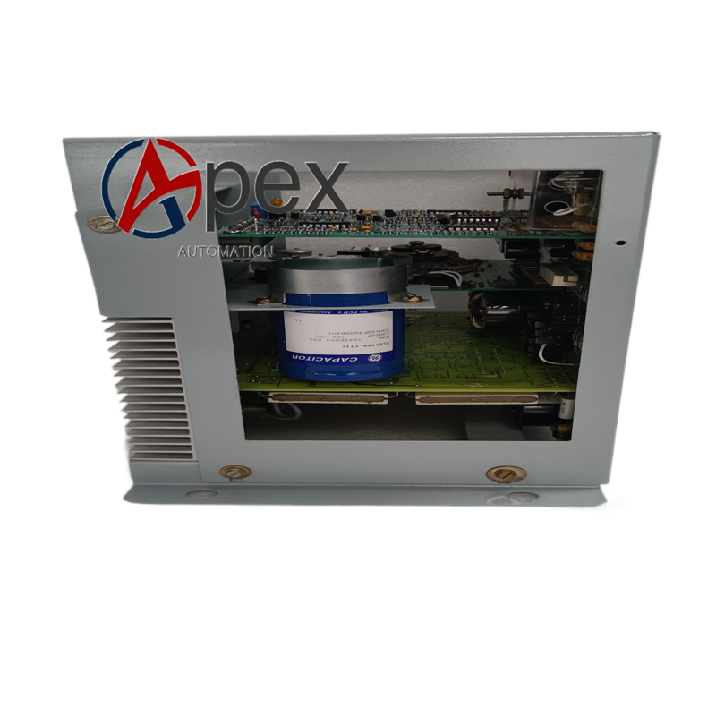
Performance Parameters Accurate multi‑rail power‑voltage monitoring precision, stable power‑sequence control logic execution, rapid power‑fault detection response capability.
Material Composition Multilayer glass‑fiber epoxy printed circuit board. Voltage monitoring sampling components, sequence‑logic integrated circuits, fault signal buffer devices. Multi‑pin plug‑in connectors. Metal screw mounting hardware. Conformal protective coating layer.
Structural Characteristics Rectangular flat PCB assembly. PPre‑drilled screw mounting holes for chassis bracket fixation. PCB layout separates high‑voltage power‑monitoring area and low‑voltage logic area.
Working Principle Auxiliary DC control power supplies on‑board circuit. Multi‑group power‑rail sampling signals from power unit enter board terminals. On‑board sampling circuit detects real‑time voltage value of each power rail.
Installation Requirements Cut off DS3820 chassis total main power and auxiliary control power before replacement. Take strict anti‑static protection during handling. Fasten DS3820PSCB1C1B onto chassis mounting bracket with mounting screws. Fully insert and lock all plug‑in connectors. Restore chassis power supply, complete power‑on sequence test and power‑fault simulation verification.
Usage Notes Anti‑static operation requirements must be followed. Powered hot‑swap operation is forbidden. Prevent mechanical scratch damage to conformal coating protective layer. Do not apply over‑range voltage to power‑monitoring input terminals.




There are no reviews yet.