

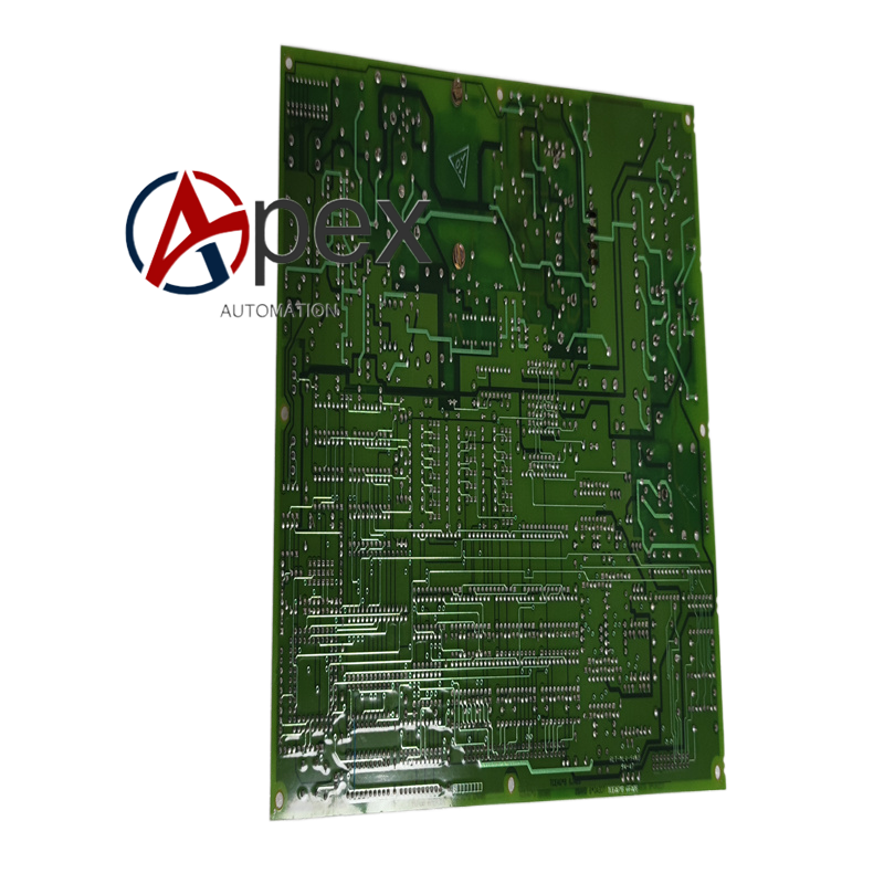

Technical Specifications Multi‑channel exciter analog input and output interfaces, Mark V back‑plane bus connector, auxiliary DC power supplied by chassis back‑plane. Operating temperature 0 ℃ to +60 ℃, storage temperature ‑40 ℃ to +85 ℃, relative humidity 5%‑95% non‑condensing. Conformal coating PCB protection. Mark V plug‑in form factor.
Functional Features Acquires analog voltage and current feedback signals from generator exciter equipment. Completes filtering and amplitude adjustment for exciter measurement signals. Converts digital excitation control commands from main CPU into analog output signals for exciter power hardware. Provides hardware over‑voltage protection for each analog channel. Supports excitation‑loop signal fault self‑diagnosis.
Application Scenarios BNE‑revision spare replacement exciter analog board for GE Mark V turbine‑generator control systems, used for power plant generator excitation control system overhaul and spare‑part renewal.
Performance Parameters Precise exciter analog signal sampling accuracy, stable analog control output, good noise‑suppression performance for excitation loop signals.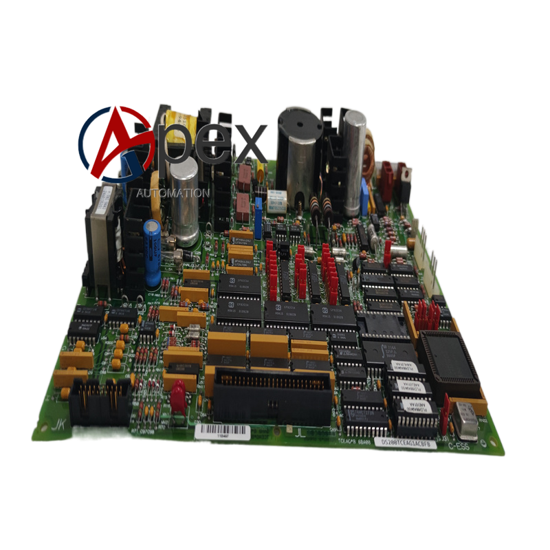
Material Composition Multilayer glass‑fiber epoxy printed circuit board with BNE‑revision component configuration. Analog signal filter and conversion components, surge protection devices. Gold‑plated Mark V back‑plane edge connector. Front metal panel equipped with status LED indicators and fixing screws. Conformal protective coating layer.
Structural Characteristics Standard Mark V chassis plug‑in board dimension. Rear gold‑plated edge connector interfaces with Mark V back‑plane bus. Front metal panel mounts status LED indicators and fastening hardware. PCB layout realizes physical separation between high‑amplitude exciter signal tracks and low‑voltage logic circuit area.
Working Principle Board draws operating power from Mark V chassis back‑plane. On‑board hardware monitors analog channel fault condition.
Installation Requirements Insert DS200TCEAG1BNE into corresponding chassis slot, tighten front‑panel fixing screws. Restore chassis power supply, run system power‑on self‑test and excitation control‑loop functional verification test.
Usage Notes Prevent mechanical scratch damage to conformal coating protective layer. Only install into compatible GE Mark V turbine‑generator control chassis.




There are no reviews yet.