

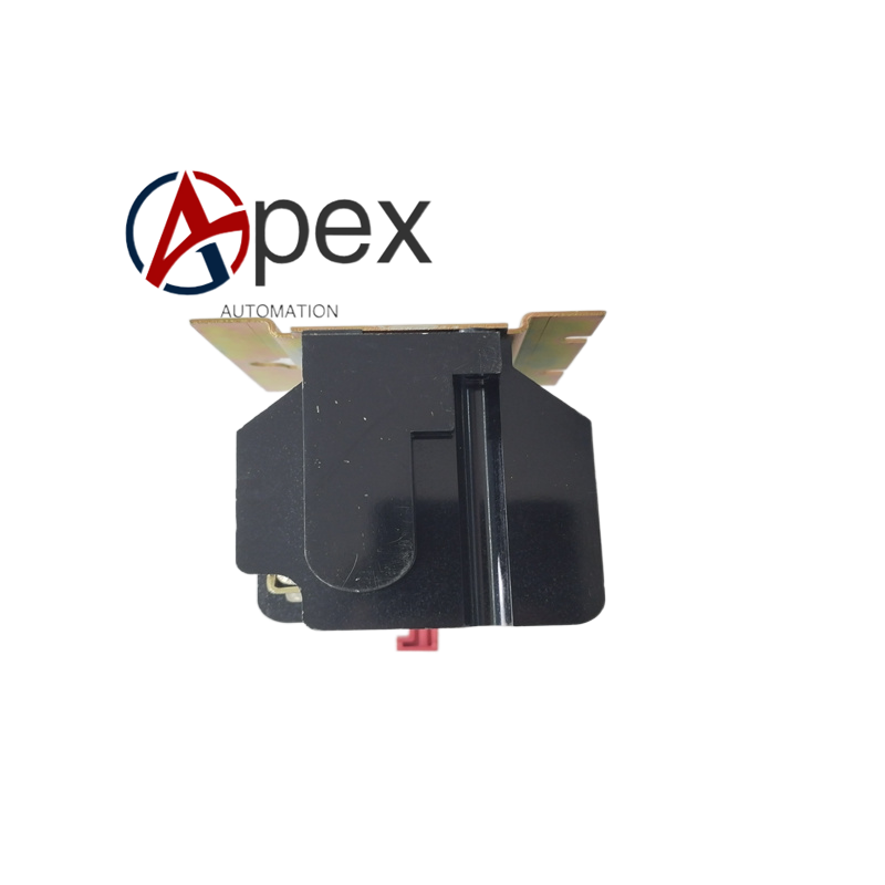

Technical Specifications Control coil voltage rating, multiple groups of isolated relay contact outputs. Operating ambient temperature ‑25 ℃ to +60 ℃, storage temperature ‑40 ℃ to +85 ℃, relative humidity 5%‑95% non‑condensing. DIN‑rail mounting mechanical structure.
Functional Features Low‑voltage control signal energizes internal coil to actuate relay contact sets. Provides multi‑group independent isolated contact outputs for interlock logic, alarm signal output and small‑power circuit switching. Realizes electrical isolation between control coil side and contact output side.
Application Scenarios Auxiliary logic switching component for power distribution cabinets, motor control centers and industrial control panels, used for power‑plant and manufacturing‑site control‑logic implementation.
Performance Parameters Reliable contact switching capacity, stable coil pull‑in and release characteristic, qualified mechanical and electrical operating life.
Material Composition Flame‑retardant plastic housing. Electromagnetic coil assembly, magnetic iron‑core components. Silver‑alloy relay contact sets, spring‑driven linkage mechanism. Screw‑type wiring terminals, DIN‑rail clamping hardware.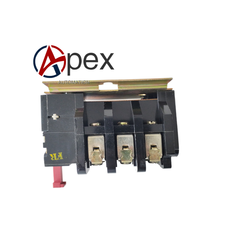
Structural Characteristics Compact DIN‑rail relay module dimension. Coil control terminals and contact output terminals are separated on housing surface. Internal electromagnetic drive assembly actuates contact sets. Built‑in DIN‑rail clip for cabinet installation fixation.
Working Principle Input control voltage energizes internal coil and generates magnetic force. Magnetic force drives iron‑core and linkage to change relay contact state. After coil power cuts off, reset spring returns contacts back to original status. Isolation structure separates control coil circuit from contact load circuits.
Installation Requirements Cut off coil control power and contact‑side load power before installation. Snap relay onto cabinet DIN‑rail. Complete coil‑side control wiring and contact‑side load wiring, tighten screw terminals. Apply control voltage, verify relay pull‑in action and contact‑state change.
Usage Notes Respect coil rated voltage and contact rated load capacity. Do not exceed contact switching current and voltage rating. Avoid dusty and corrosive installation environment.




There are no reviews yet.