

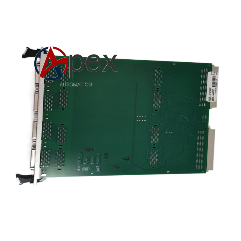

Technical Specifications VME back‑plane bus interface, multiple peripheral signal interfaces, on‑board memory chips, auxiliary DC working power supplied by VME chassis. Operating temperature 0 ℃ to +60 ℃, storage temperature ‑40 ℃ to +85 ℃, relative humidity 5%‑95% non‑condensing. Standard VME form‑factor plug‑in board.
Functional Features Implements VME bus protocol processing and bus resource management. Executes local data calculation and data caching. Completes bidirectional data exchange between VME back‑plane and peripheral functional boards. Supports hardware initialization and system‑level diagnostic functions. Handles interrupt signal processing from other VME modules.
Application Scenarios Spare replacement processor board for GE VME‑bus industrial control systems, widely used for power plant and heavy‑industry automation equipment maintenance.
Performance Parameters Stable VME‑bus protocol processing performance, high‑speed internal data throughput, reliable interrupt handling capability, consistent long‑time running stability.
Material Composition Multilayer glass‑fiber epoxy printed circuit board. Main processing chip, memory integrated circuits, VME bus driving components, peripheral interface circuits. Gold‑plated VME back‑plane edge connector. Front‑panel metal bracket with status LED indicators.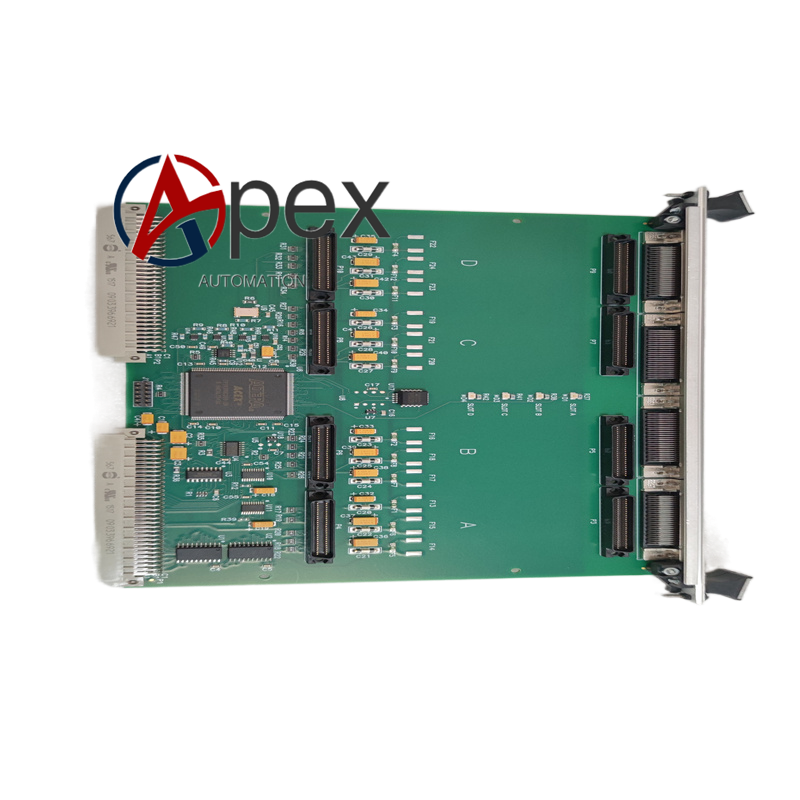
Structural Characteristics Standard VME‑size circuit board. Rear gold‑plated edge connector mates with VME chassis back‑plane bus. Front metal panel includes status LED indicators and fixing screw holes. Components arranged on PCB follow VME mechanical specification.
Working Principle Board draws operating power from VME chassis back‑plane. Main processing chip communicates with other VME modules via back‑plane bus. It processes system data, manages bus access and responds to hardware interrupt signals. Peripheral data are buffered and forwarded between different functional modules inside VME chassis.
Installation Requirements Insert AVME‑9668 board into designated VME chassis slot, tighten front‑panel fixing screws. Restore chassis power supply, complete system power‑on initialization and bus communication verification test.
Usage Notes Must install into compatible VME‑bus chassis system. Hot‑swap operation under powered chassis condition is forbidden.




There are no reviews yet.