

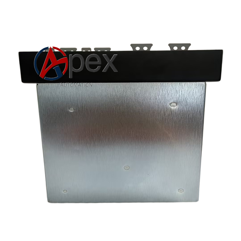

Technical Specifications Multi‑channel signal input and output channels, back‑plane system bus interface. Auxiliary DC working power obtained from chassis back‑plane. Operating temperature 0 ℃ to +60 ℃, storage temperature ‑40 ℃ to +85 ℃, relative humidity 5%‑95% non‑condensing. Plug‑in chassis mounting form.
Functional Features Receives field side switching and analog signals. Completes signal isolation and level conversion. Transforms field signal to signal level compatible with main control system bus. Transmits control commands from main unit to field side equipment. Supports channel hardware fault diagnosis.
Application Scenarios Spare‑part replacement component for GE industrial control system, widely used in power plant and heavy‑industry automation site maintenance.
Performance Parameters Reliable signal isolation performance, stable signal level conversion precision, fast channel fault detection response.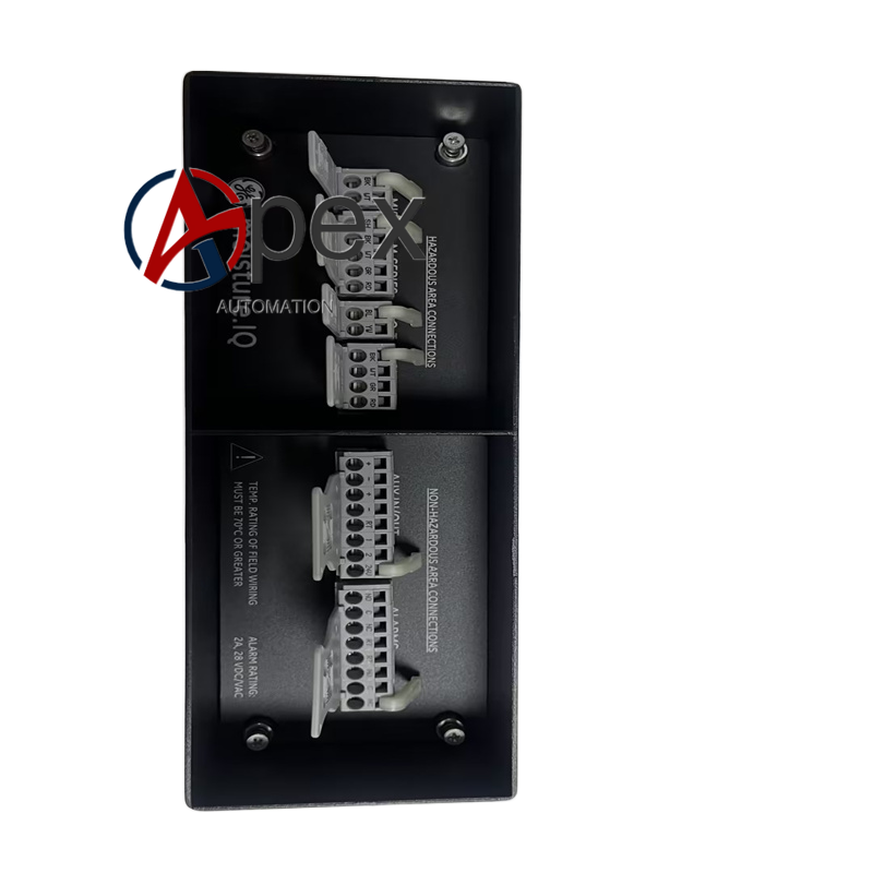
Material Composition Flame‑retardant plastic module housing. Multilayer glass‑fiber epoxy printed circuit board. Signal isolation and conditioning circuit components. Gold‑plated back‑plane bus contact connectors. Chassis locking buckle hardware.
Structural Characteristics Standard plug‑in module shape. Rear‑edge connector mates with chassis back‑plane bus. Front‑panel screw terminals for field signal wiring. Module locking buckle fixes unit into chassis slot. Front‑panel status LED indicators display channel working state.
Working Principle Module obtains working power from chassis back‑plane bus. Field input signals pass through isolation and level conversion circuit, converted signal data is transmitted to main control unit via back‑plane bus. Control commands from main unit go through isolation circuit and output to field equipment.
Installation Requirements Power‑off equipment chassis power supply before installation. Insert module into designated chassis slot and lock buckle. Connect field signal cables onto front‑panel screw terminals. Restore chassis power supply, perform signal loop test to verify input and output channel function.
Usage Notes Only apply for matched compatible chassis system. Field signal wiring shall avoid excessive surge voltage interference. Forbid hot‑swap under powered condition.




There are no reviews yet.