

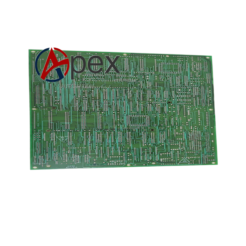

Technical Specifications Multi‑channel DC signal input and output interfaces, internal system bus connector, auxiliary DC working power supply. Operating temperature 0 ℃ to +60 ℃, storage temperature ‑40 ℃ to +85 ℃, relative humidity 5%‑95% non‑condensing. PCB conformal coating protection.
Functional Features Acquires DC bus voltage and current feedback signals from power unit. Conditions DC analog signal level to match main controller acquisition range. Receives control commands from main control board and distributes driving signals to power functional modules. Provides hardware over‑voltage and over‑current signal detection. Transmits status and fault feedback signals back to main processor via internal bus. Supports hardware channel self‑diagnosis.
Application Scenarios Original spare replacement board for GE high‑power DC drive and power conversion equipment. Used for equipment overhaul and maintenance in energy and metallurgical industry sites.
Performance Parameters Stable DC analog signal conditioning accuracy, fast fault signal response, reliable internal bus signal transmission performance.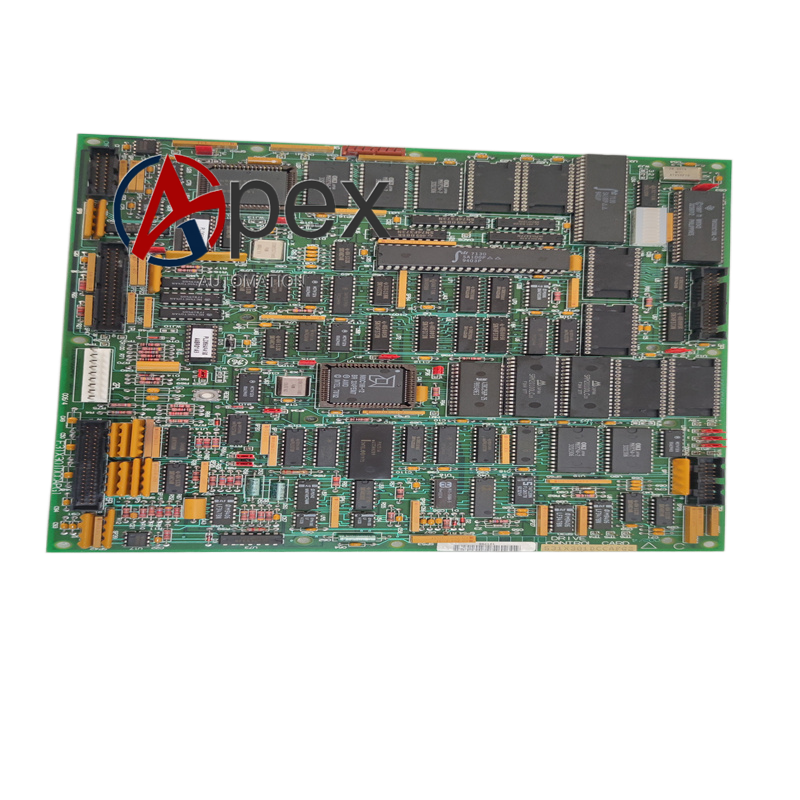
Material Composition Multilayer glass‑fiber epoxy printed circuit board. DC signal conditioning components, signal buffer and peripheral circuit assemblies. Multi‑pin plug‑in connectors, metal screw mounting hardware. Conformal protective coating layer.
Structural Characteristics Rectangular PCB layout. Power‑unit‑side signal connectors and main‑controller‑side bus connectors are arranged on different board edges. Pre‑drilled screw mounting holes for cabinet bracket fixation. PCB layout separates high‑voltage signal area and low‑voltage logic area.
Working Principle Processed signals are sent to main control board. Control commands from main controller pass through buffer circuit and output driving signals to power modules. Fault detection circuit monitors loop status and feeds abnormality information back to main processor.
Installation Requirements Fasten circuit board onto cabinet mounting bracket with screws. Fully insert and lock all plug‑in connectors. Restore auxiliary power supply, carry out DC signal loop test and channel self‑check verification.
Usage Notes Observe high‑voltage safety operation procedures. Prevent mechanical scratch to conformal coating surface.




There are no reviews yet.