

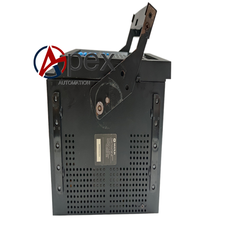

Technical Specifications Three‑phase low‑level current and voltage measurement inputs, multi‑channel digital inputs, relay output contacts, P5 communication interface. Supports multi‑channel RTD sensor access. Operating ambient temperature ‑20 ℃ to +65 ℃, storage temperature ‑40 ℃ to +85 ℃, relative humidity 5%‑95% non‑condensing. Front‑panel LCD display and operation keypad.
Functional Features Provides overload, locked‑rotor, phase unbalance, phase loss, ground fault and motor jam protection. Receives RTD signals to monitor motor winding and bearing temperature. Stores fault snapshot, start‑up records and operating trend data. Completes three‑phase electrical parameter metering. Supports local manual operation and remote control via communication bus. Configurable alarm and trip output logic.
Application Scenarios Motor protection unit for industrial sites where instrument transformer outputs low‑level secondary signals, applied in power auxiliary workshops, chemical production lines and motor control centers.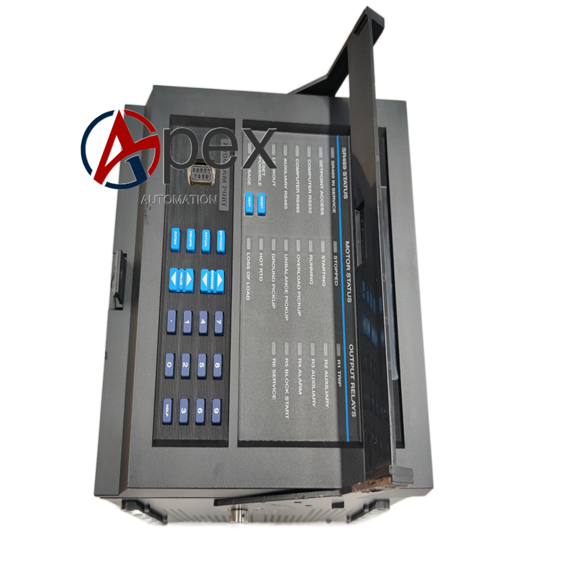
Performance Parameters Optimized low‑level signal sampling accuracy, flexible configurable protection curves, reliable fault data storage and stable communication transmission capability.
Material Composition Flame‑retardant plastic housing. Main CPU processing board, low‑level signal dedicated conditioning circuit, relay output assemblies. Front‑panel LCD and keypad assembly. Screw‑type field wiring terminal blocks. Metal mounting clip hardware.
Structural Characteristics Standard cabinet panel‑mount housing. Front panel equipped with LCD display, status LED indicators and setting push‑buttons. Rear side arranges low‑level CT/PT input terminals, digital I/O terminals and communication wiring terminals. Mounting clips fix relay into cabinet panel cut‑out.
Working PrincipleInternal conditioning circuit optimizes signal processing, processor samples electrical data and calculates motor thermal status continuously.
Installation Requirements Complete low‑level CT, PT, digital I/O wiring strictly follow official wiring diagram. Connect RTD and communication field cables. Power‑on unit, input motor parameters and protection setting values, complete function verification test.
Usage Notes Must match low‑level secondary output instrument transformers. RTD and communication wiring adopt shielded cables.




There are no reviews yet.